Contents — find the section you need
Background and reading guide
Background Units used in specifications, such as voltage, current, distance and time.
Fundamentals · Explanations of principles, structure and trade-offs.
A magnetometer converts the strength and direction of a magnetic field — Earth's own field, or one produced by a nearby object — into an electrical signal. At its core is a phenomenon from solid-state physics: when a current or an electron's spin sits inside a magnetic field, the voltage or electrical resistance it produces changes according to that field's strength and direction. Reading that change precisely lets you quantify the direction of an otherwise invisible field of magnetic field lines. Where cameras, LiDAR, and radar actively or passively work with light and radio waves, a magnetometer always deals with something that is simply already there — Earth's magnetic field itself — making it one of the few sensors that can keep returning an absolute-direction external reference indoors, underwater, or underground, anywhere GPS can't reach, as long as it has power. From a smartphone's electronic compass app, to yaw-angle drift correction in the 9-axis sensors built into drone and self-driving-car IMUs, to spacecraft attitude control, it is a foundational component built into almost every piece of electronics that needs to know which way is which.
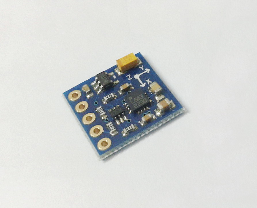 Honeywell HMC5883L (3-axis digital compass IC)
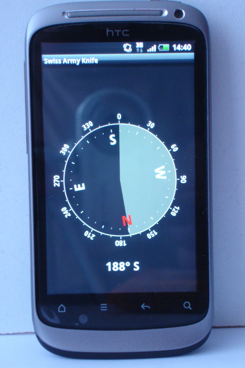 A smartphone electronic compass app
Image: Honeywell HMC5883L(Ctg4Rahat, CC BY 3.0)/ Smartphone electronic compass app(Zirguezi, CC0), Wikimedia Commons.


Principles: Four Physical Phenomena for Measuring Earth's Magnetic Field — Hall Effect, AMR, GMR, Fluxgate
The term "magnetometer" covers roughly four distinct physical operating principles internally. All four are actually mass-produced today as consumer and industrial 3-axis magnetometer chips.
The Hall Effect — A Transverse Voltage Produced by Current and a Magnetic Field
When a current I flows through a thin semiconductor film and a magnetic field B is applied perpendicular to that current, the Lorentz force deflects the charge carriers in a direction orthogonal to both the current and the field, producing a voltage difference (the Hall voltage V_H) along that direction.
Here n is the carrier density, e is the elementary charge, and t is the film's thickness. Because the Hall voltage is proportional to the field strength, amplifying and digitizing it lets you measure the magnetic field directly. The underlying phenomenon is the Hall effect itself, discovered in 1879 by Edwin Hall, then a graduate student at Johns Hopkins University — an effect over 140 years old that is still working away inside today's smartphone chips. Bosch Sensortec's magnetometers use a Hall-effect-based structure the company calls "FlipCore," and the BMM150 is its flagship representative.
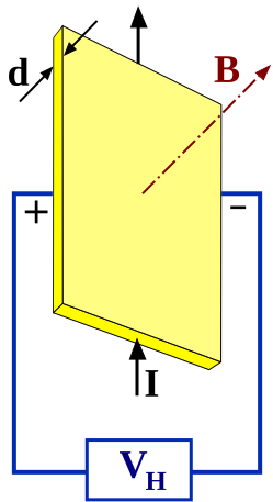
Image: Diagram of the Hall effect(Gregors, CC BY-SA 3.0), Wikimedia Commons. The Hall voltage V_H appears in a direction orthogonal to both the current I and the magnetic field B.

AMR (Anisotropic Magnetoresistance) — Electrical Resistance That Changes with Magnetization Direction
A ferromagnetic material's (an iron-nickel alloy, for example) electrical resistance shifts slightly with the angle \theta between its internal magnetization direction and the direction of current flow. The change in resistance is roughly proportional to \cos^2\theta, and using that relationship to detect an external field's direction is the AMR (Anisotropic Magnetoresistance) approach. The phenomenon itself is older than the Hall effect — William Thomson (Lord Kelvin) discovered it in iron and nickel in 1856. Because the practical resistance swing it produces is larger than what a Hall-effect sensor delivers, AMR devices offer better sensitivity, and Honeywell's HMC5883L is a 3-axis digital compass IC that explicitly uses this "Anisotropic Magnetoresistive technology."
GMR (Giant Magnetoresistance) — A Multilayer Film That Produces an Order-of-Magnitude Bigger Resistance Swing
GMR (Giant Magnetoresistance) extends the same basic idea as AMR but differs from it in both mechanism and scale. Stack ferromagnetic and nonmagnetic metals into a multilayer structure with each layer just a few nanometers thick, and whether adjacent magnetic layers' magnetization directions are parallel or antiparallel dramatically changes how much spin-dependent scattering the electrons undergo, swinging electrical resistance by tens of percent. Where conventional AMR produces only a few percent change in resistance, GMR can deliver a change approaching 50% — which is exactly why it earned the name "giant." Cost still keeps the Hall effect and AMR at the center of mainstream 3-axis compass ICs, but GMR and TMR (Tunnel Magnetoresistance) remain the technology lineage used where higher sensitivity is required — high-sensitivity magnetometers and hard-disk read heads among them. Its discovery is covered in the history section below.
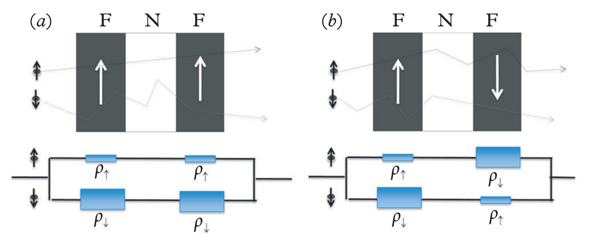
Image: Schematic of a GMR multilayer structure(K. M. Krishnan, CC BY-SA 4.0), Wikimedia Commons. Ferromagnetic layers (green) and nonmagnetic layers (gray) are stacked alternately; electrical resistance changes dramatically depending on the layers' relative magnetization directions.

Fluxgate — Saturating a Magnetic Core for High Precision
Where the Hall effect, AMR, and GMR all exploit the physical properties of a semiconductor or thin film directly, the fluxgate approach uses electromagnetic induction. An excitation coil wound around a soft-magnetic core (a high-permeability core) carries an AC current that periodically drives the core into and out of magnetic saturation. When the core is unsaturated it readily admits an external field; once saturated it pushes that external field back out — and picking up this nonlinear response with a sense coil produces harmonic components (chiefly the second harmonic) proportional to the strength of the external field. The added complexity of the underlying principle buys higher precision and lower noise than Hall-effect- or AMR-based semiconductor chips typically achieve, which is why fluxgate remains the active choice today for geomagnetic observation satellites and high-precision marine and aviation magnetometers.
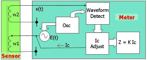
Image: Diagram of the fluxgate magnetometer principle(BacLuong, public domain), Wikimedia Commons. An excitation coil periodically saturates the core, and a sense coil reads the harmonic components of the induced voltage that vary with the external field.

Geomagnetism and Heading: Declination, the Gap Between Magnetic North and True North
Earth is itself a giant magnet — convection in its outer core (the geodynamo) generates a field that blankets the surface. An "electronic compass" built on a magnetometer detects the direction of this geomagnetic vector's horizontal component and calls it magnetic north. But the magnetic pole (the north magnetic pole) does not coincide with the geographic North Pole (true north), and it drifts slightly year by year, so the magnetic north measured at a given location differs from true north by an amount called "magnetic declination." Declination can range from a few degrees to over twenty depending on location and year, so a practical electronic compass corrects for it using its own position (latitude and longitude) and the current time, referencing a geomagnetic model such as the WMM (World Magnetic Model) — jointly revised every five years by NOAA's National Centers for Environmental Information and the British Geological Survey. GPS alone can't provide heading (you only learn your direction of travel once you're moving), so a magnetometer, which can return a heading instantly even while stationary, complements GNSS in exactly this respect.
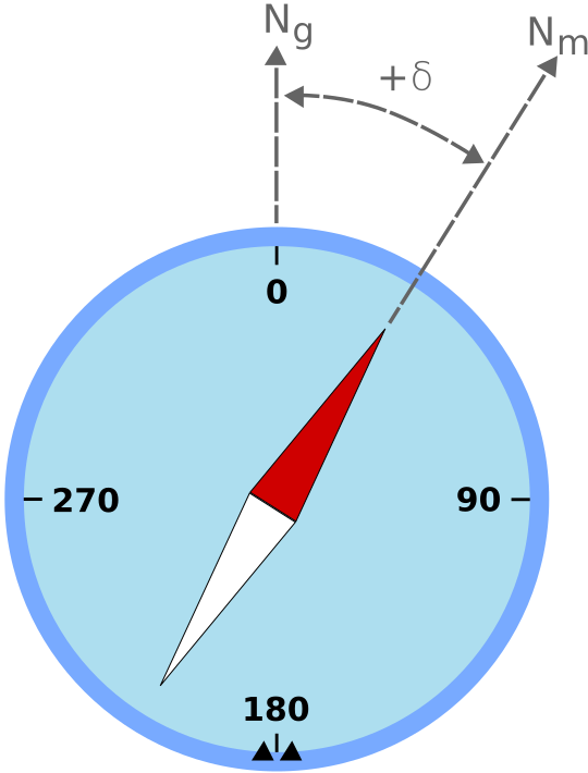
Image: Diagram explaining magnetic declination(Odder, CC BY-SA 3.0), Wikimedia Commons. Declination is the angular difference between True North and Magnetic North.

Hard-Iron and Soft-Iron Error, and Calibration
Mount a magnetometer on an actual vehicle — a robot, drone, or car — and magnetic distortion produced by the vehicle itself mixes in alongside Earth's own field. This distortion falls broadly into two categories.
- Hard iron error: A "fixed" magnetic offset produced by a motor's permanent magnets, a speaker, or current-carrying wiring. It shows up as the sensor output's origin shifting away from Earth's true magnetic zero point — plot the 3-axis output and you get a sphere whose center is offset from the origin.
- Soft iron error: An error, varying with heading, produced when high-permeability parts — iron, nickel — distort the surrounding field. It shows up as the 3-axis output distribution deforming from a sphere into an ellipsoid.
Calibration works by rotating the vehicle through every orientation while collecting raw magnetometer data, then combining sphere fitting (hard-iron correction — estimating the offset) with ellipsoid fitting (soft-iron correction — correcting scale and tilt) to derive the transformation matrix and offset vector that map the distorted ellipsoid back onto a sphere centered at the origin. This procedure is standard fare in application notes published by instrumentation makers such as Analog Devices and VectorNav — an unavoidable step in any real magnetometer implementation. A 2025 paper, "Joint Magnetometer-IMU Calibration via Maximum A Posteriori Estimation" (arXiv:2505.16662, Chuan Huang, Gustaf Hendeby, Isaac Skog), treats the magnetometer's and IMU's calibration parameters together with sensor orientation as jointly unknown and solves for them via maximum a posteriori estimation, reporting a 20-30% accuracy improvement and an order-of-magnitude speedup over prior methods — one example showing calibration itself remains an active research topic today.
Fusion with an IMU: Attitude and Heading Estimation via AHRS
An IMU (Inertial Measurement Unit) integrates acceleration and angular velocity to derive attitude, but relying on integrated angular velocity alone lets the yaw angle (the vehicle's heading, its rotation about the vertical axis) drift without bound over time. An accelerometer, which can use gravity's direction as a reference, can correct roll and pitch drift, but it has no cue at all for rotation about the vertical axis. This is where the magnetometer earns its keep. Because Earth's magnetic vector points in a constant horizontal direction (setting aside local distortion), combining the magnetometer's output with a known attitude lets you periodically reset yaw-angle drift.
An algorithm that estimates absolute attitude from a "9-axis" configuration — a 3-axis accelerometer, 3-axis gyroscope, and 3-axis magnetometer combined — is called an AHRS (Attitude and Heading Reference System), and the Madgwick filter and Mahony filter are its two representative implementations. The Madgwick filter is structured like a proportional controller, using an error gradient derived from the accelerometer and magnetometer to correct the gyroscope's attitude estimate, and it delivers high accuracy in a 9-axis configuration; the Mahony filter instead corrects gyro bias using proportional-integral control, making it well suited to implementation on small microcontrollers with limited computing resources. In both cases, a 6-axis configuration (accelerometer plus gyroscope only) that lacks a magnetometer cannot constrain yaw to an absolute value — it can only track relative rotation — which is precisely why a magnetometer gets paired with an IMU in the first place.
Comparing Specs Across Key Products
| Product | Maker | Sensing Method | Range | Resolution | Interface | Notes |
|---|---|---|---|---|---|---|
| BMM150 | Bosch Sensortec | Hall effect (FlipCore) | ±1300µT (X/Y axes), ±2500µT (Z axis) | 0.3µT | I2C/SPI | Low power (170µA low-power preset), the standard choice for e-compass use |
| LIS3MDL | STMicroelectronics | Magnetoresistive | ±4/±8/±12/±16 gauss (selectable) | 16-bit output | I2C/SPI | Four selectable full-scale ranges, -40 to 85°C operation |
| HMC5883L | Honeywell | AMR | ±8 gauss | 0.005 gauss | I2C | The pioneering 3-axis digital compass IC, widely used on Arduino breakout boards |
| AK09918C | Asahi Kasei Microdevices | Hall effect | ±32 gauss (wide dynamic range) | — | I2C | Ultra-compact 4-pin WLCSP package, for smartphones and wearables |
| MLX90393 | Melexis | Hall effect (Triaxis+IMC) | ±4.8mT or higher at highest-sensitivity setting | Depends on programmable gain setting | I2C/SPI | Micropower operation via variable duty cycle from 0.1-100%, also used for proximity-magnet position sensing |
Bosch's BMM150 uses a Hall-effect-based structure built on the company's proprietary FlipCore technology, with a low-power design clearly aimed at e-compass applications. STMicro's LIS3MDL offers the flexibility of four selectable full-scale ranges from ±4 to ±16 gauss and is widely adopted from industrial equipment to drones. Honeywell's HMC5883L has long held de facto standard status as an AMR-based 3-axis digital compass IC, and it remains widely distributed today as the core chip inside the cheap breakout boards (GY-271 and similar) that are a staple of the Arduino/Raspberry Pi hobbyist robotics and drone community. Asahi Kasei Microdevices' AK09918C, made by a Japanese manufacturer, leans on an extremely small 4-pin WLCSP (wafer-level chip-scale package) to target smartphones and wearables. Belgium's Melexis builds the MLX90393 by combining the Hall effect with its proprietary Triaxis technology and an IMC (Integrated Magnetic Concentrator) — its micropower operation, tunable via duty cycle from 0.1% to 100%, is the headline feature. Beyond geomagnetic compass use, it's also deployed as a contactless position sensor detecting the position and angle of a nearby permanent magnet, making it a highly versatile product.
History: From Ore Prospecting to Submarine Hunting to the Moon
Trace today's high-precision magnetometers back to their origin and you land on oil-company ore-prospecting technology. The fluxgate magnetometer was a cheap, easy-to-use technology developed in the 1930s by Victor Vacquier of Gulf Oil for mineral-deposit surveying. In 1941, with the outbreak of World War II, Vacquier moved to Columbia University's Airborne Instruments Laboratory and joined research applying this fluxgate technology to submarine detection. The result was a device called the "MAD" (Magnetic Airborne Detector), mounted on aircraft and ships to detect the magnetic anomaly produced by a shallow-submerged enemy submarine. MAD entered operational use in December 1942 and was used by both Japanese and American anti-submarine forces.
After the war, the fluxgate magnetometer found a second life in space exploration. Beyond observing Earth's own magnetic field, the Apollo program used fluxgate magnetometers deployed on the lunar surface to observe the Moon's residual magnetization and its interaction with the solar wind. The path this civilian ore-prospecting technology took — through wartime anti-submarine warfare and on to lunar science — is a textbook case of sensor technology's civilian-military crossover history.
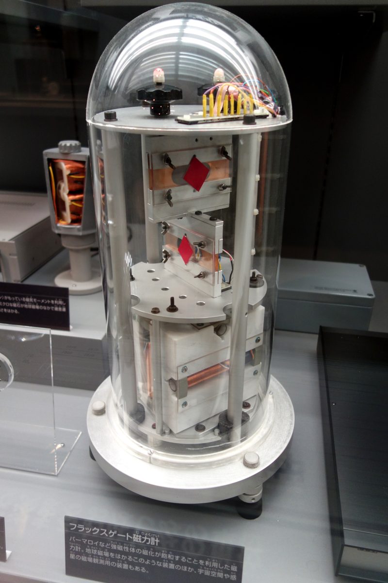
Image: A fluxgate magnetometer of the type carried on Apollo lunar surface probes(Daderot, CC0), Wikimedia Commons. On exhibit at the National Museum of Nature and Science (Tokyo).

Magnetoresistance and the Nobel Prize That Transformed the Hard Disk
The discovery of GMR (Giant Magnetoresistance) stands out even among magnetometer history for its drama. In 1988, a group led by France's Albert Fert and a group led by Germany's Peter Grünberg independently discovered the phenomenon. Fert's group observed a resistance change approaching 50% in a multilayer structure of stacked iron and chromium layers, while Grünberg's group confirmed a change of roughly 10% in an iron-chromium-iron trilayer structure. Given that the prior magnetoresistance effect (AMR) produced resistance changes of at most a few percent, this "giant" swing was a stunning figure at the time — and the name GMR itself was coined by Fert.
The discovery reached commercial application in under a decade. In 1997, once hard-disk read heads exploiting the GMR effect were implemented, the hard disk's annual growth rate in storage density — previously around 60% a year — leapt to nearly 100%. The large-capacity storage underpinning today's smartphones and data centers rests on this GMR-head-driven revolution in storage density. In 2007, Albert Fert and Peter Grünberg jointly received the Nobel Prize in Physics "for the discovery of Giant Magnetoresistance." Even measured by the speed from basic-physics discovery to commercialization to a Nobel Prize, GMR occupies a singular place in magnetometer history. As the 2025 joint magnetometer-IMU calibration study mentioned above shows, research into improving magnetometer accuracy remains ongoing nearly 40 years after this discovery in condensed-matter physics.
Case Study: Stopping a Tumbling CubeSat Using Nothing but Earth's Magnetic Field — B-dot Control
One fascinating case where magnetometers — whether several at once or a single unit — really earn their keep is attitude control on the CubeSat, a class of very small satellites. A CubeSat is often injected into orbit tumbling at an unintended angular velocity right after separating from its rocket. Before it can point solar panels at the sun or a communications antenna at Earth, that rotation first has to be stopped — a process called detumbling.
The algorithm used here, called "B-dot control," relies on nothing but a 3-axis magnetometer and magnetorquers — coil-based actuators. It computes the rate of change over time (the derivative, "B-dot") of the Earth's magnetic field vector B as measured by the magnetometer, then drives current through the magnetorquers to produce a magnetic moment in the direction that cancels that change. The torque produced by interaction with Earth's magnetic field gradually damps the vehicle's rotation, and after a few orbits the CubeSat settles into a stable attitude. The simplicity of using the output of a single 3-axis magnetometer for both angular-velocity estimation and control commands — without even a gyroscope — is exactly why the approach suits CubeSats, where low cost, low power, and low mass are non-negotiable. It's a case that stands in sharp contrast to a car's array of many sensors: a magnetometer alone completing autonomous attitude stabilization end to end.
Parameters That Determine Performance
- Matching sensing method and range to the application: For electronic-compass applications that measure Earth's field (roughly 25-65µT at the surface), sensitivity optimized for the geomagnetic range — as in the BMM150 (±1300/2500µT) or HMC5883L (±8 gauss = 800µT) — is plenty, while a product like the MLX90393, built with an eye toward detecting a nearby permanent magnet's position, carries a much wider range of ±4.8mT or more plus programmable gain. Whether the application is "heading detection via Earth's field" or "position detection via a nearby magnet" fundamentally changes what range design you should be shopping for.
- Resolution and noise floor: How finely you can resolve heading traces directly back to resolution specs like the BMM150's 0.3µT or the HMC5883L's 0.005 gauss (=0.5µT). In a robot's self-localization, where a magnetometer corrects an IMU's yaw drift, coarse resolution becomes the bottleneck on correction accuracy itself.
- Power consumption and duty control: How finely you can throttle operation when continuous measurement isn't needed — as with the BMM150's low-power preset (170µA) or the MLX90393's variable duty cycle from 0.1-100% — governs battery life in power-constrained vehicles like wearables or CubeSats.
- Tolerance to hard-iron/soft-iron error and mounting position: However high-performance the chip, mounting it near a motor, speaker, or metal frame introduces large errors. Careful sensor placement at the implementation stage, combined with careful sphere/ellipsoid-fitting calibration, matters more for real-world accuracy than the datasheet spec.
- Package size and mounting constraints: An ultra-compact package like the AK09918C's 4-pin WLCSP becomes the deciding factor in devices — smartphones, wearables — where board area is severely constrained. In industrial applications, ease of mounting or a wide operating-temperature range (the LIS3MDL's -40 to 85°C, for example) often takes priority instead.
- Integration design with an IMU: Whether you use it as a standalone magnetometer chip or as part of an integrated 9-axis IMU module changes the implementation effort considerably. In applications using an AHRS algorithm to correct yaw drift, time synchronization and sampling-rate consistency with the accelerometer and gyroscope tend to be the practical bottleneck more than the magnetometer's standalone performance.
Reference Links
- Bosch BMM150 Datasheet (Bosch Sensortec official PDF)
- Bosch BMM150 Product Flyer (Bosch Sensortec official PDF)
- STMicroelectronics LIS3MDL Datasheet (ST official PDF)
- STMicroelectronics LIS3MDL Product Page
- Honeywell HMC5883L Datasheet (Adafruit-hosted PDF)
- Melexis MLX90393 Product Page
- Melexis MLX90393 Datasheet (Melexis official PDF)
- Hard & Soft Iron Correction for Magnetometer Measurements (Analog Devices EngineerZone)
- Magnetometer Hard & Soft Iron Calibration (VectorNav)
- Joint Magnetometer-IMU Calibration via Maximum A Posteriori Estimation (arXiv:2505.16662)
- Magnetic anomaly detector (Wikipedia, on Vacquier and MAD's history)
- A WWII submarine-hunting device helped prove plate tectonics (Science News)
- 2007 Nobel Prize in Physics press materials (NobelPrize.org)
- 2007 Nobel Prize Honors GMR Discovery (American Physical Society)
- Madgwick Orientation Filter (AHRS library official documentation)
- Mahony Orientation Filter (AHRS library official documentation)
- CubeSat B-dot Detumbling Control (Hindawi/International Journal of Aerospace Engineering)
- Hall effect (Wikipedia, on Edwin Hall's discovery)
Can magnetometer heading be trusted unchanged indoors?
Steel, wiring currents, and motors disturb the field. Calibration does not remove every location-dependent disturbance; check field magnitude and consistency.
Current step · 11 / 21 · Sensors & Hardware
Comments
Please log in to post a comment
No comments yet.