Contents — find the section you need
Background and reading guide
Background Units used in specifications, such as voltage, current, distance and time.
Fundamentals · Explanations of principles, structure and trade-offs.
An IMU (Inertial Measurement Unit) combines an accelerometer and a gyroscope (angular-rate sensor) to directly measure a vehicle's own translational acceleration and rotational angular velocity. Unlike "exteroceptive" sensors such as cameras, LiDAR, and GNSS — which all reference some external light, radio signal, or landmark — an IMU is a fully self-contained "proprioceptive" sensor. That is its greatest strength: it can keep estimating attitude and displacement even in environments with zero external information, such as inside a tunnel or indoors where GNSS never reaches. It is a foundational sensor used across nearly every autonomous mobile system — attitude estimation in self-driving cars, flight control in drones, inertial odometry inside a robot's SLAM (simultaneous localization and mapping) stack — and it is also built into consumer devices by the billions, from smartphone screen-rotation detection to motion-controlled game controllers.
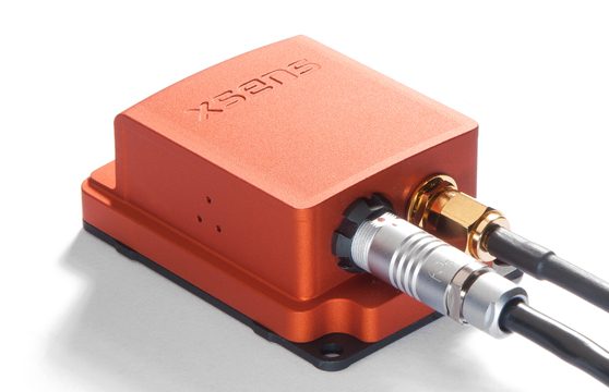 Xsens MTi-G (integrated GNSS/INS model)
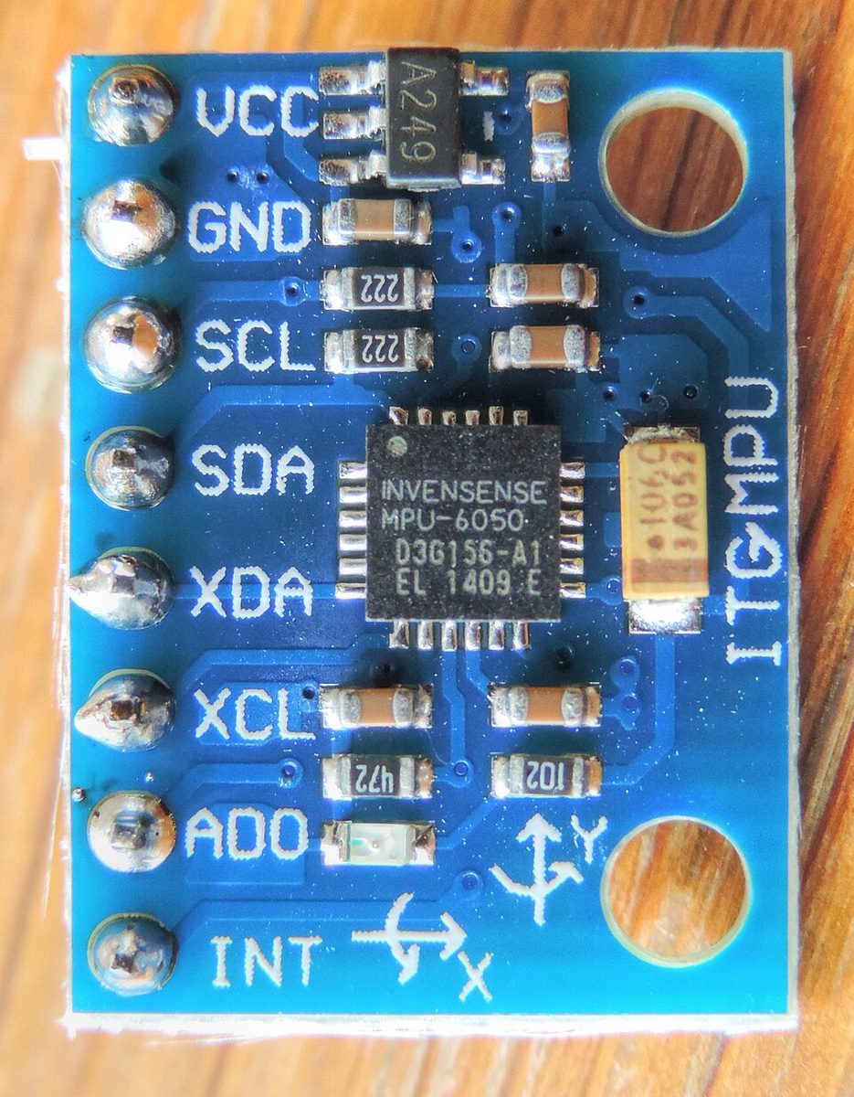 InvenSense MPU-6050 (GY-521 breakout board)
Images: Xsens MTi-G (Kallap85, CC BY-SA 4.0) / GY-521 MPU-6050 module (Nevit Dilmen, CC BY-SA 3.0), Wikimedia Commons. The MPU-6050 is the consumer-grade IMU chip discussed later in this article.


Principle: estimation by integration, and drift as an inescapable fate
An IMU can only directly measure "rates of change" — acceleration and angular velocity — so recovering position or attitude requires integrating those signals over time. Integrating angular velocity \omega(t) yields attitude angle \theta(t); double-integrating acceleration a(t) yields position p(t).
The catch is that every sensor's output carries some constant bias error b plus random noise. If the bias stays at a constant value b, the resulting angle error grows linearly with time t — but because acceleration bias is double-integrated, the resulting position error grows with t squared.
This is what "drift" really is, and it is exactly why an IMU alone cannot sustain accurate long-duration self-localization: without periodic correction from an external absolute reference — GNSS, a camera, or similar — the errors just keep growing. That is why an IMU is rarely deployed alone; it is almost always fused with GNSS/INS integration or visual odometry (typically via an extended Kalman filter that predicts with the IMU and corrects with the exteroceptive sensor).
How a MEMS gyroscope works: tuning forks and the Coriolis force
Nearly every mass-produced IMU today is MEMS-based (micro-electro-mechanical system). The classic MEMS gyroscope structure is the "tuning-fork vibratory gyroscope": a microscopic proof mass etched into a silicon substrate is driven to oscillate at a fixed frequency and amplitude by a set of drive electrodes. When the sensor itself rotates while the mass is oscillating, a Coriolis force acts along the axis orthogonal to both the drive direction and the rotation axis, displacing the proof mass slightly in that perpendicular direction. Sense electrodes pick up this tiny displacement as a change in capacitance, converting it into an electrical signal proportional to angular velocity. MEMS accelerometers work on the same basic principle — an external force displaces the proof mass slightly, and that displacement is read out as a capacitance change. Unlike older mechanical gyroscopes built around spinning rotors, a MEMS device's only moving part is a vibrating mass, which is exactly what makes it so amenable to low-cost, miniaturized mass production.
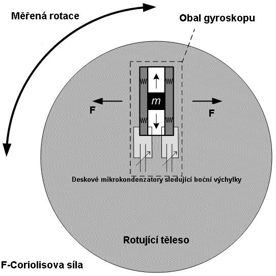
Image: Schematic diagram of a MEMS gyroscope (David Vlachý, CC BY-SA 3.0 / GFDL), Wikimedia Commons. Illustrates the basic tuning-fork MEMS gyroscope structure: rotation applied to an oscillating mass produces a Coriolis force that displaces it along the perpendicular axis.

Characterizing noise: Allan variance
IMU noise cannot be captured by a single number — its character changes with time scale, and multiple distinct error sources dominate at different scales. At short timescales, quantization noise dominates; at medium timescales, angle random walk (ARW) dominates; at long timescales, bias instability and rate random walk (RRW) dominate. The standard technique for separating and characterizing these is Allan-variance analysis, standardized under IEEE-STD-952-1997. The minimum point on the Allan-variance curve is the "in-run bias stability," one of the most important figures on any IMU datasheet.
IMU grades: from consumer to strategic
Required precision varies enormously by application, and the industry has settled on a rough grading scale keyed to gyroscope bias stability.
| Grade | Gyro bias stability | Approx. position error per hour | Typical use |
|---|---|---|---|
| Consumer | ≥30 deg/h | >11,000 km | Smartphones, game controllers, drone attitude control (assuming GNSS is available) |
| Industrial | 10-100 deg/h | 1,100-11,000 km | Industrial robots, UGVs, camera-gimbal stabilization |
| Tactical | 1-10 deg/h | 110-1,100 km | UAV/UGV inertial navigation, backup navigation during GNSS outages |
| Intermediate | 0.01-1 deg/h | 1.1-110 km | Precision agriculture machinery, precision survey, high-end autonomous-driving prototypes |
| Navigation | <0.01 deg/h | <1.1 km | Aircraft and ship inertial navigation systems (INS) |
| Strategic | <0.001 deg/h | <110 m | Long-duration, uncorrected navigation for submarines and missiles |
The gap between consumer grade and tactical grade spans tens to hundreds of times in bias stability, and that gap translates directly into product price — anywhere from a chip costing a few hundred yen to a module costing hundreds of thousands of yen. For self-driving cars with continuous GNSS access, consumer-to-industrial grade is often sufficient; for applications where GNSS is unavailable for extended periods — tunnels, underground, battlefield conditions — tactical grade or higher becomes mandatory.
Comparing key products by spec
| Product | Maker | Grade | Gyro bias stability | Accel bias stability | Notable feature |
|---|---|---|---|---|---|
| Xsens MTi-2 (600-Series) | Xsens (Movella) | Industrial | 6 deg/h | 40µg | Flexible line-up up to GNSS/INS integration (MTi-670/680) |
| Bosch BMI088 | Bosch Sensortec | Consumer-to-industrial | Under 2 deg/h | Not disclosed (derived from automotive-grade lineage) | High vibration robustness, built for drones and robotics |
| Analog Devices ADIS16500 | Analog Devices | Industrial-to-tactical | 6.25 deg/h | 16µg | Six axes plus attitude computation packed into a 15×15×5mm BGA |
| Honeywell HGuide HG4930 | Honeywell | Tactical | 0.25 deg/h | Not disclosed | FOG (fiber-optic gyro) class accuracy realized in MEMS form, under 3W power draw |
| VectorNav VN-100 / VN-300 | VectorNav | Industrial-to-tactical | Not disclosed (reported as fused IMU/AHRS output) | Not disclosed | VN-300 achieves 0.15° static heading accuracy via dual GNSS antennas |
| InvenSense MPU-6050 | InvenSense (now TDK) | Consumer | Not disclosed (consumer chips typically don't publish bias stability) | Not disclosed | Six-axis single-chip IMU; the archetypal consumer IMU used in phones like the Nexus 7 |
Xsens sells its products by "series," spanning the tiny 1-Series, a bare IMU output (MTi-610), an AHRS with onboard attitude estimation (MTi-630), and a full GNSS/INS integration model reaching RTK-level positioning (MTi-670/680) — a wide spread of grades even within the 600-Series alone. The MTi-2 spec above is one representative example of Xsens's IMU-line spec sheet. Bosch's BMI088 openly targets drones and robotics, having been announced at CES 2018. It repurposes the vibration-robust gyroscope technology Bosch honed for automotive electronic stability systems (ESP and the like), giving it a low-drift characteristic where the temperature coefficient of offset (TCO) stays under 15 mdps/K. Analog Devices' ADIS16500 packs a six-axis sensor and an attitude-computation processor into a single BGA module — pricier than a bare chip, but it saves a great deal of integration effort. Honeywell's HG4930 markets itself explicitly as delivering "FOG (fiber-optic gyro) class performance at MEMS size and MEMS price," built on the company's two decades of inertial-navigation heritage as a tactical-grade product.
The Wii Remote and the Dawn of Consumer MEMS Accelerometers
MEMS accelerometers and gyroscopes now cost a few hundred yen apiece, but the device that truly cemented their place in consumer electronics was Nintendo's Wii Remote, released in 2006. Nintendo began developing the Wii around 2001, licensing motion-sensing patents from Gyration Inc. along the way, and ultimately settled on Analog Devices' three-axis MEMS accelerometer, the ADXL330. STMicroelectronics was also involved in the project, and by some reports development ran from Nintendo's first meeting with the company to shipping product in just nine months — remarkably fast. Two-axis MEMS accelerometers already existed at the time, but adding a third axis brought real technical difficulty. The Wii Remote's commercial success cemented the trend of MEMS inertial sensors being embedded into mass-market consumer devices — phones and game consoles alike.
The product that came to best symbolize that trend afterward was InvenSense's MPU-6050. It pioneered the "six-axis IMU" — a three-axis gyroscope plus three-axis accelerometer fused onto a single chip — and shipped on the main boards of many smartphones and tablets, including Google's Nexus 7 (2012). Thanks to its low cost and easy availability, it has remained a staple part in the Arduino and Raspberry Pi hobbyist robotics and drone-building community. Individual autonomous-mobile-robot projects like newbot are no exception — reaching for an MPU-6050-family IMU for an initial bring-up test is a common first step.
Xsens's own corporate history is a story worth telling on its own. Founded in Enschede, Netherlands, in 2000 by Casper Peeters and Per Slycke, the company built its reputation with inertial sensor suites for motion capture, such as "MVN." It was acquired by semiconductor giant Fairchild Semiconductor in 2014, then came under ON Semiconductor when ON acquired Fairchild in 2016. In 2017, semiconductor maker mCube acquired Xsens; mCube rebranded itself as Movella in 2021, and the Xsens brand's products are now sold under the Movella umbrella. Over roughly two decades, the company evolved from a standalone sensor maker into a company spanning motion capture, wearables, and industrial IoT — all built on "movement data."
On the academic side, research aimed at machine-learning-based correction of standalone IMU drift is active. "AirIMU: Learning Uncertainty Propagation for Inertial Odometry" (arXiv:2310.04874), published in 2023, proposes learning the uncertainty — the propagation of error itself — directly from raw IMU data to improve inertial-odometry accuracy. Data-driven IMU error-characterization approaches, going beyond classical Allan-variance-based noise models, are a recurring theme reported continuously at robotics conferences in recent years.
Parameters that determine performance
- Bias stability: The smaller this number, the longer attitude estimation can be sustained without external correction from GNSS or similar sources (i.e., the slower drift accumulates). As the grading table above shows, the gap between consumer grade (≥30 deg/h) and tactical grade (1-10 deg/h) spans tens of times, and that gap directly determines how long autonomous navigation can continue once GNSS is lost
- Noise density / angle random walk: This directly determines attitude-estimation accuracy in vibration-heavy environments — vehicles, drones, legged robots. Higher noise density makes it easier to mistake momentary vibration for real vehicle motion, inflating estimation error. This is exactly the component Allan-variance analysis separates out as the short-to-medium-timescale error source
- Whether GNSS is integrated: For applications moving outdoors over long distances at high speed — vehicles, drones — choosing a model like the VectorNav VN-300 or Xsens MTi-670/680, which integrates GNSS up to RTK-level positioning, lets the system periodically reset accumulated drift while sustaining high-accuracy self-localization. For an indoor-only robot, GNSS never reaches it, so this integration feature loses most of its point
- Environmental and vibration robustness: A tactical-grade product like the Honeywell HG4930 operates across a wide -54 to 85°C temperature range. As with Bosch's BMI088 repurposing automotive-grade vibration-robustness technology, in applications exposed to drone-motor or vehicle-engine vibration, noise behavior under vibration often matters more in practice than the raw bias-stability figure alone
- Sampling rate and responsiveness: For applications needing fast feedback control, like drone flight control, the IMU's output rate (the VectorNav VN-300 reaches up to 400Hz) directly determines the responsiveness of the attitude-control loop itself
- Cost-versus-size trade-off: A consumer chip like the MPU-6050 is available for a few hundred yen in a few millimeters square, while a tactical-grade product like the HG4930 costs on the order of hundreds of thousands of yen and demands a correspondingly larger footprint. Choosing a grade well beyond what the required accuracy actually calls for is rarely rational, whether judged by cost, power draw, or mounting-space footprint
Quantifying drift with the sampling period
An implementation does not integrate the continuous-time equations directly. It updates attitude, velocity, and position every sampling period \Delta t. After transforming acceleration into the navigation frame and removing gravity, let a_k be the measured acceleration, b_a the accelerometer bias, and n_{a,k} its noise. The simplest discrete update is
If gyro bias b_g is constant, attitude error follows \delta\theta\simeq b_g t. A gyro with 1 deg/h bias stability, left without an external correction for 60 seconds, therefore has an idealized angle error of 1\times(60/3600)=0.0167 deg. Real hardware adds temperature changes, non-orthogonality, and vibration-rectification error, so this calculation is not a guaranteed accuracy figure. The practical lesson is to log \Delta t, temperature, and estimated bias together; otherwise an integration problem and a sensor fault can look identical.
Figure — The integration order makes bias error grow rapidly over long intervals. The curves are explanatory, not measurements from a particular IMU.
Does a gyroscope directly output roll, pitch, and yaw?
It measures angular velocity in the sensor frame. Orientation estimation needs coordinate relationships, integration, and bias handling.
References
- Xsens MTi product selector (Xsens official)
- Xsens 25-year history (Xsens/Movella official)
- Bosch BMI088 product page (Bosch Sensortec official)
- Bosch BMI088 datasheet (Bosch Sensortec official PDF)
- Analog Devices ADIS16500 product page
- Honeywell HGuide HG4930 product page
- Honeywell HG4930 feature article (Unmanned Systems Technology)
- VectorNav VN-300 product page
- VectorNav VN-100 product page
- Definition of "tactical grade" for a MEMS IMU (Analog Devices EngineerZone)
- Wii Remote (English Wikipedia, on the ADXL330 selection)
- InvenSense (English Wikipedia)
- AirIMU: Learning Uncertainty Propagation for Inertial Odometry (arXiv:2310.04874)
- Allan-variance analysis of MEMS gyroscopes (NCBI/PMC)
Current step · 6 / 21 · Sensors & Hardware
Comments
Please log in to post a comment
No comments yet.