Contents — find the section you need
Background and reading guide
Background Units used in specifications, such as voltage, current, distance and time.
Fundamentals · Explanations of principles, structure and trade-offs.
An actuator converts electrical energy into mechanical motion — it's a robot's "muscle." Turning a joint, spinning a wheel, extending an arm: every moving part of an autonomous mobile robot or manipulator is driven by an actuator. The terms "BLDC motor," "stepper motor," and "servo motor" often get discussed as if they were parallel choices, but they actually conflate two different axes. BLDC and stepper are "motor types" defined by how and where electromagnetic force is generated (construction), while servo is, in most cases, a "control architecture" — a BLDC motor paired with an encoder and driver to close the loop — and the two aren't mutually exclusive alternatives. With that framing in mind, what actually matters when choosing an actuator in practice comes down to a tradeoff among three axes — torque, response, and control complexity/cost — and this article compares those three axes using real product numbers.
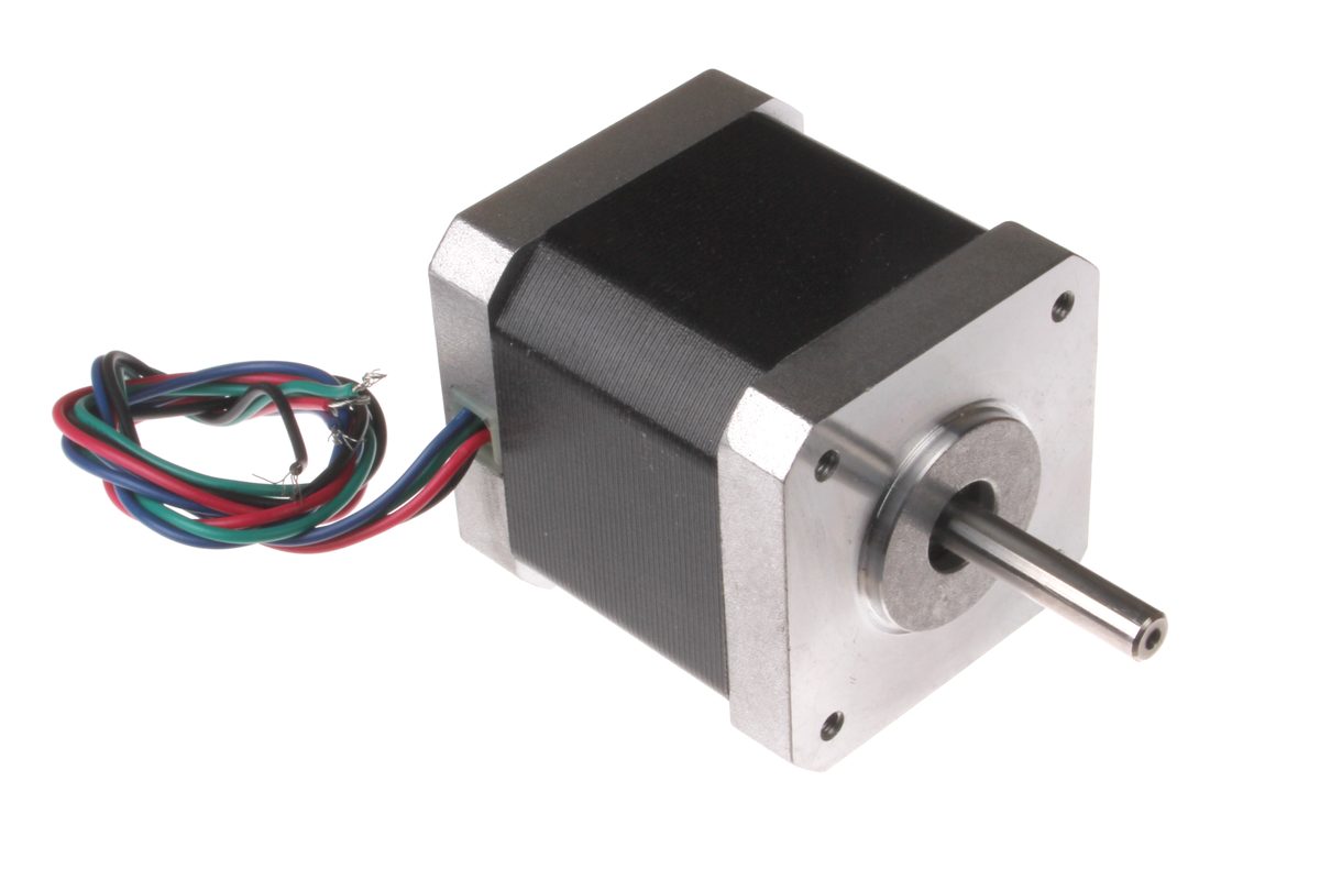 NEMA17 stepper motor
 Outrunner-type BLDC motor (3-wire)
Images: Nema 17 Stepper Motor (oomlout, CC BY-SA 2.0) / Outrunner (1sfoerster, CC BY-SA 3.0), both Wikimedia Commons. Not the exact products compared in the text (StepperOnline/T-Motor units), but representative examples of the same motor construction. No suitable individual photo turned up on Wikimedia Commons for servo motors (Dynamixel/Yaskawa units), so none is included.


Principle: torque and back-EMF, common to every electromagnetic motor
BLDC, stepper, and servo all rest on the same underlying electromagnetic principle. Passing current through a coil placed in a magnetic field generates a force (the Lorentz force) on the conductor, and this becomes the torque that spins the rotor. The generated torque T is roughly the product of the motor's torque constant k_t and the winding current I.
As the rotor spins, the coil itself moves through the magnetic field, generating a back-EMF e proportional to angular velocity \omega.
In an ideal motor, k_t and k_e come out equal once units are aligned, and this is where a motor's basic torque-speed characteristic comes from: more current means more torque, and higher rotation speed pushes the back-EMF closer to the supply voltage, making further acceleration harder. The differences among BLDC, stepper, and servo boil down to how this electromagnetic force is generated (construction) and how it's controlled (architecture) — nothing more.
The construction axis: BLDC motors and stepper motors
The BLDC motor (brushless DC motor) consists of a rotor with permanent magnets and a stator with multi-phase windings that get switched electronically. Where a conventional brushed DC motor switches current direction through a mechanical contact (brushes and a commutator), a BLDC senses rotor position via Hall sensors or back-EMF detection and switches the winding energization pattern electronically through semiconductor switches (an inverter). With no mechanical wear parts, it favors long life, high efficiency, and high-speed rotation, making it the mainstay for applications built around continuous rotation. There's also a choice in how rotor position gets detected: a "sensored" design that physically places Hall sensors in the stator can accurately track position even at standstill or low speed, at the cost of more parts and expense. A "sensorless" design, which infers position from the back-EMF waveform induced in the windings, cuts parts count but suffers reduced position-estimation accuracy right after standstill or at very low speed, where back-EMF is small. Most drone motors go sensorless precisely because that weakness matches the use case well — once airborne, the motor holds a rotation speed well above that low-speed regime.
The stepper motor advances the rotor by discrete angular steps, energizing the stator's magnetic poles in sequence. Most products run without an encoder, in open-loop control, tracking position purely by "how many pulses were sent." The angle the rotor advances per energization switch is called the step angle; a representative 1.8°-step motor divides one full revolution into 200 steps (360° ÷ 1.8°).
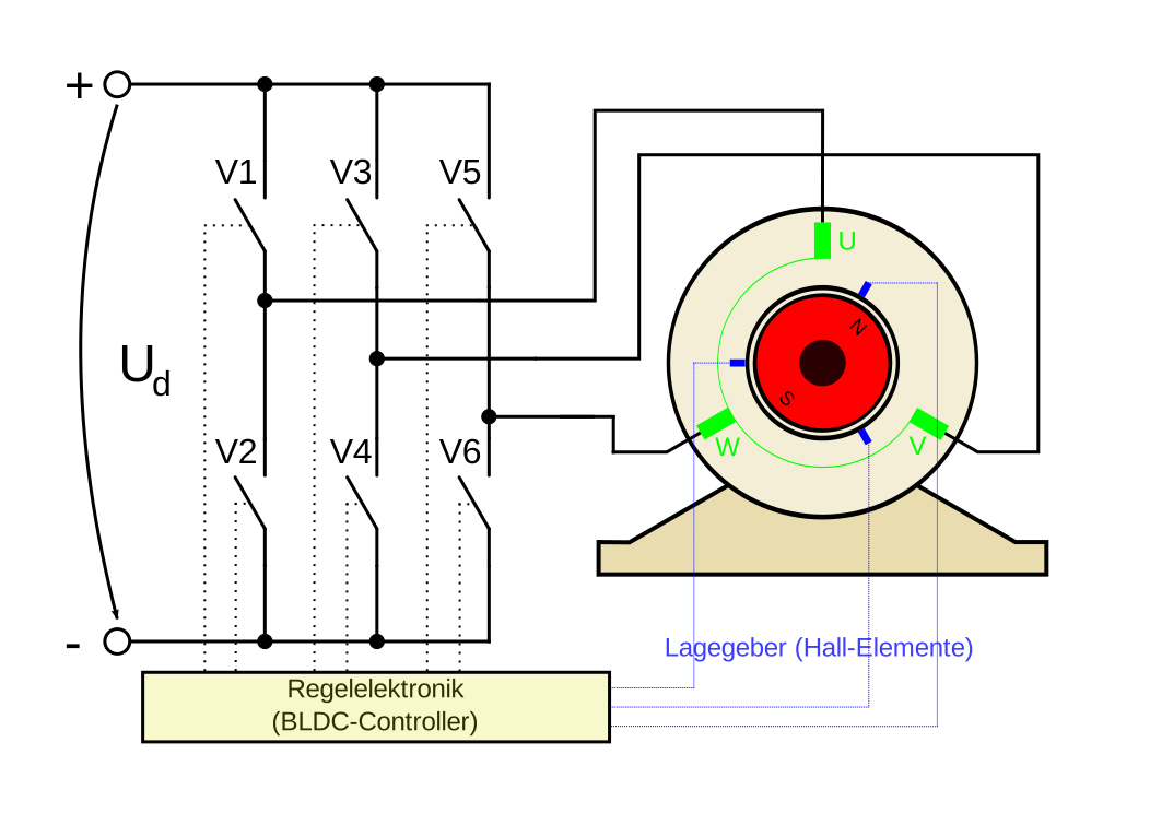 BLDC motor construction
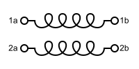 Bipolar stepper motor windings
Images: EC-Motor (Dermartinrockt, public domain) / Stepper Motor Bipolar Coils (public domain), both Wikimedia Commons.


Being open-loop carries the risk of a stall (a mismatch between pulses sent and actual rotation, causing a position error), but in exchange the circuitry is simple and cheap. Being able to generate substantial holding torque at a standstill just by maintaining energization is another characteristic that stands in contrast to BLDC, which assumes continuous rotation.
Even within BLDC, control approach splits further depending on how the winding energization pattern is switched. The simplest, trapezoidal (six-step) commutation, switches only two of the three phases on/off at a time — the circuit stays simple, but torque ripple tends to appear at the moment commutation switches. Sinusoidal drive (FOC, Field-Oriented Control), in contrast, keeps sinusoidal current flowing through all three phases based on rotor angle, keeping generated torque smooth. It costs more compute than trapezoidal drive, but for applications where low-speed vibration or noise matters (robot joints, precision equipment), FOC has become the standard choice. Even within the same BLDC "construction," this choice of "control method" alone shifts the tradeoff between smoothness of response and controller complexity.
The control-architecture axis: servo as a name for "closing the loop"
"Servo motor" doesn't refer to a specific motor construction — it refers to a control architecture that pairs a motor with an encoder (a position/velocity sensor) and a driver (control circuitry), feeding back the difference between target and measured value to track a target. Most commercial "servo motor" products are, internally, a BLDC motor (or, for an AC servo, a synchronous motor) with closed-loop control layered on top. The basic control law is PID control, which computes the manipulated variable u(t) from the error e(t) against the target value as follows:
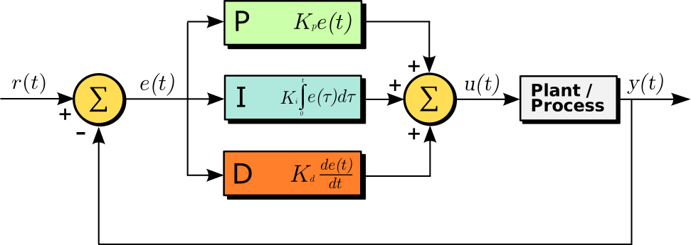 PID control feedback loop
Image: PID controller block diagram (Arturo Urquizo), Wikimedia Commons (CC BY-SA 3.0).

The proportional term (K_p e) responds to the current error itself, the integral term eliminates accumulated error, and the derivative term responds to how fast the error is changing. Because the encoder continuously monitors actual position/velocity and keeps applying corrections, the system can keep tracking the target even under disturbances like load changes. The values of each gain (K_p, K_i, K_d) are rarely settled by theory alone — reaching usable control performance requires "tuning," the trial-and-error work of watching the actual response waveform on real hardware. Gains too small mean sluggish tracking; too large means oscillation or instability, so this tuning effort itself becomes part of the cost of adopting a servo. There's also an intermediate product category — the "closed-loop stepper," which adds an encoder to a stepper motor to close the loop — and its existence confirms that the open-loop/closed-loop axis and the BLDC/stepper axis are genuinely independent of each other.
Key product specification comparison
| Product | Type | Rated/max torque | Speed/resolution | Voltage/current | Notes |
|---|---|---|---|---|---|
| Maxon EC-i 40 | BLDC motor (industrial) | Max continuous torque 171mNm, stall torque 2760mNm | No-load speed ~4,700–18,000rpm (voltage-dependent) | 15–48V | 170W rated output |
| T-Motor MN5006 (KV300) | BLDC motor (drone outrunner) | Recommended thrust 0.8–1kg (continuous), max thrust 3.2kg | 24N28P configuration, weight 108g | 4–6S LiPo compatible, peak current 26A | Antigravity series for long flight endurance |
| StepperOnline 17HS24-2104S | Stepper motor (NEMA17, open-loop) | Holding torque 65Ncm | Step angle 1.8° (200 steps/rev) | 2.1A/phase | 42×42×60mm |
| Robotis DYNAMIXEL XM430-W350-T | Servo motor (robot joint) | Stall torque 4.1Nm, rated torque 0.82Nm | Resolution 4096 (12-bit, 0.088°) | 12V | 82g weight, supports current-based position control |
| Yaskawa SGM7G | Servo motor (industrial AC servo) | Rated torque up to 95.2Nm | Rated speed 1500rpm, 24-bit encoder | — | Sigma-7 series' highest-torque class |
Within the same Sigma-7 lineup, the SGM7J (max 2.39Nm, 3000rpm) and SGM7P (max 4.77Nm, 3000rpm) are positioned for smaller, lighter-duty applications, while the SGM7G caps speed at 1500rpm in exchange for pushing torque up to 95.2Nm — a model clearly tuned toward "high torque, low speed." Sharing the same manufacturer and the same encoder technology (24-bit) while splitting into multiple models by whether torque or speed takes priority shows that "servo motor" as a product category doesn't have a single performance profile — it spans a range of torque/speed tradeoffs matched to use case.
Comparing the two BLDC products shows how differently "optimization" can point even within the same "BLDC motor" category. Maxon's EC-i 40 is designed as an industrial actuator prioritizing a wide torque and speed range and flexible voltage range, while the T-Motor MN5006 pushes to the extreme a question specific to flight vehicles — how much thrust can be squeezed out of a 108g weight (power-to-weight ratio). The stepper motor, StepperOnline's 17HS24-2104S, achieves 65Ncm of holding torque with simple constant-current drive at 2.1A/phase, and being able to hold that torque at a standstill without an encoder is a characteristic neither BLDC nor servo shares. Between the two servo products, the robot-joint-oriented DYNAMIXEL XM430 packs a 4096-resolution encoder into a compact 12V/82g package, while the industrial Yaskawa SGM7G is engineered as a distinctly different weight class, delivering a staggering 95.2Nm of torque in a practical 1500rpm operating range.
For reference, the drivetrain of the newbot project uses none of BLDC, stepper, or servo — it's a brushed DC gear motor with an encoder (12V, 100RPM), PWM-driven through a motor driver (Cytron MDD10A). Its control, though, isn't real-time closed-loop velocity control in the "servo" sense described here; it's a feedforward-style setup where a known speed command (mm/s) is sent, matched against the encoder's measured value, and used to pre-calibrate the conversion factor from speed command to PWM duty cycle. For a relatively simple differential two-wheel drive, this suggests a design judgment that pushing a cheap general-purpose gear motor to usable precision through pre-calibration alone was the more sensible cost/complexity tradeoff, rather than bringing in the always-on feedback control that a dedicated servo product offers.
History: brush wear in vacuum, the heart of the floppy disk, and cybernetics born from anti-aircraft aiming
BLDC: the discovery that brushes last only minutes in a vacuum — During World War II, rapid brush wear and failure in rotating equipment aboard aircraft above 30,000 feet (about 9,100m) became one starting point for brushless research. In the mid-1950s, H. D. Brailsford presented the first DC motors to be called "brushless," demonstrating that removing brushes could deliver surprisingly long-lived operation. On the theory side, T. G. Wilson and P. H. Trickey put forward the concept of solid-state commutation using transistors in their 1962 paper "D.C. Machine With Solid State Commutation." The decisive finding came from NASA: a 1966 technical report revealed that conventional carbon-brush commutator life amounted to mere minutes when operated in vacuum. The vacuum of space itself, in other words, ruled out brushed motors — and by 1965, space-qualified BLDC motors (ranging from 1 watt up to half a horsepower) were already in service, circulating oxygen in the Apollo Lunar Module and driving the coolant pumps on the Saturn I-B and Saturn V. By 1974, BLDC motors had become the standard choice for Apollo's life-support blowers and for circulating oxygen in the lunar Portable Life Support System, and NASA engineers came to expect maintenance-free operating lives of up to 10 years for space-exploration and satellite applications. A simple mechanical part — the brush — became a bottleneck under the extreme conditions of vacuum, and solving that problem pushed electronic control technology toward practical use: a textbook case of space development forging civilian technology.
Stepper motors: from relays to the floppy disk — The stepper motor's roots reportedly trace back to the stepping relay of the early 20th century (a mechanism, used in telephone exchanges among other things, that advances a contact with each pulse), with the first modern stepper motor prototype appearing in the 1920s. One key moment that spread this technology widely was its adoption in floppy disk and hard disk drives in the late 1970s. Positioning a read/write head precisely, track by track, was a good match for open-loop control's core characteristic — "pulses sent equals distance moved" — with no need for an encoder, and this opened an era of mass-producing stepper motors as the beating heart of consumer storage hardware.
Servo: anti-aircraft gun aiming gave birth to cybernetics — During World War II, the mathematician Norbert Wiener worked on the hard problem of automatically aiming anti-aircraft guns. A fast-flying aircraft would be somewhere else by the time a shell arrived, so the gun had to aim not at the plane's current position but at where it was going to be. Wiener worked out the mathematics for predicting an aircraft's trajectory from noisy radar observation data and continuously feeding that prediction back into the aiming mechanism. In the process, he noticed something about the structure itself — that the gun, the radar, and the human operator together formed a single system that sensed its own error and kept correcting it — and realized the same pattern applied to a living nervous system. That insight crystallized into his 1948 book, Cybernetics: Or Control and Communication in the Animal and the Machine. A byproduct of military technology — anti-aircraft gun aiming — went on to become the theoretical foundation for every closed-loop control system since, including the feedback control theory that today's servo motors implement directly. The skeleton of PID control — measure the error against a target, and send back a corrective action in the direction that cancels it — is, mathematically, exactly the same structure Wiener found in that heterogeneous system of gun, radar, and human operator.
A real deployment: eight BLDC motors, paired for redundancy, on one drone
A representative case of BLDC motors being "used several at a time" is the DJI Agras T50, an agricultural spraying drone. It arranges eight BLDC motors and eight propellers, two per arm across four arms, coaxially in pairs (a coaxial dual-rotor configuration), splitting the lift generated by each arm across the upper and lower motor. The benefit of this arrangement is redundancy: if one motor in a pair fails, the other has room to keep maintaining lift. Against an empty weight of about 40kg, the drone carries up to 40kg of payload for spraying or 50kg for spreading, with a takeoff weight reaching 103kg when loaded for spreading. Paired with surroundings detection (front and rear phased-array radar, a binocular vision system), it achieves an operating efficiency of 21 hectares per hour in the obstacle-dense environment of farmland. Rather than pushing the reliability of each individual BLDC motor to the limit, pairing motors to secure redundancy at the mechanism level is the design decision that underpins practical deployment of large, heavy-payload drones. Even the shared idea of "using multiple BLDC motors" means something different depending on context — a consumer quadcopter needs only the minimum four motors to secure attitude-control degrees of freedom, while an industrial drone has to simultaneously satisfy both payload lift and redundancy, changing what adding more motors is actually for.
What torque specs alone don't show — a 2025 attempt to quantify "human-level" actuation
A November 2025 paper on evaluating actuator performance for humanoid robots, "Human-Level Actuation for Humanoids" (MD-Nazmus Sunbeam), proposes a three-layer framework: a "Kinematic DoF Atlas" that standardizes per-joint coordinate systems, a "Human-Equivalence Envelope" that defines torque/power requirements benchmarked against human physical capability, and a "Human-Level Actuation Score" that aggregates them. The paper's central point is that looking only at peak-torque numbers on a spec sheet obscures a tradeoff that actually matters — raise the gear ratio and you gain torque but sacrifice response bandwidth and efficiency; keep the gear ratio low and response stays fast but you struggle to deliver the torque you need. This is the same structural problem as this article's central question of choosing among BLDC, stepper, and servo, just recurring one level down, at the choice of gear ratio — a snapshot of where the research frontier currently stands. Moving closer to direct drive (no reduction gearing) makes external forces easier to sense (higher backdrivability) but caps performance at whatever torque the bare motor can deliver; raising the gear ratio, conversely, lets you handle more torque at the cost of response speed and mechanical backdrivability. This relationship shows that the torque/response/control-method tradeoff introduced at the top of this article extends beyond the actuator alone, into the design of the whole mechanism it's built into.
Parameters that determine performance
- Torque-to-weight ratio (power-to-weight ratio): For flight vehicles like drones, what dominates isn't absolute torque but "how much thrust can be generated relative to the unit's own weight." This is exactly why the T-Motor MN5006 obsesses over its 108g weight — a fundamentally different evaluation axis from an industrial design philosophy like the Maxon EC-i 40's
- Open-loop vs. closed-loop: A stepper motor's open-loop control is cheaper and less complex, needing no encoder feedback circuitry, in exchange for stall risk. For applications where positional accuracy is critical under significant load variation — precision robot-arm work, say — an encoder-equipped servo configuration becomes the de facto requirement
- Holding torque at standstill: A stepper motor can generate substantial holding torque at a standstill just by maintaining energization, while a BLDC needs special control (keeping current flowing) to keep producing torque while stopped, which tends to raise heat-management concerns
- Response (bandwidth): A servo's closed-loop control can push response speed further through PID gain tuning, but the ceiling is set by the motor's own electrical time constant (the ratio of inductance to resistance) and mechanical time constant (the ratio of inertia to damping) — no amount of clever control law can, in principle, produce a response faster than the motor's own physical characteristics allow
- Resolution: As with the DYNAMIXEL XM430's 4096-count resolution (0.088° increments), a servo's positioning precision maps directly to its encoder resolution. A stepper motor's resolution is set by its step angle (typically 1.8°, further subdividable via microstepping drive) — a fundamentally different determining factor
- Cost and control complexity: An industrial AC servo (Yaskawa SGM7G class) delivers high precision and high torque but demands a dedicated driver and tuning effort in return. In early prototyping, the low cost and control simplicity of a stepper motor like StepperOnline's is often prioritized instead
- Torque ripple by commutation method: Even for the same BLDC motor, trapezoidal drive and FOC (sinusoidal drive) produce very different degrees of torque smoothness. For applications where low-speed vibration directly affects image quality or motion precision — a camera gimbal, a robot joint — FOC is nearly mandatory, while an application dominated by high-speed rotation, like a drone propeller, rarely runs into trouble even with trapezoidal drive
- Securing reliability through redundancy: As the DJI Agras T50's coaxial dual-rotor configuration shows, a design decision to parallelize multiple units at the mechanism level and tolerate the failure of one — rather than pushing individual motor reliability to its limit — is a realistic option for large, high-payload applications
- Drive voltage and current margin: The Maxon EC-i 40 can be driven across a wide 15–48V range, with rated torque and speed rising as applied voltage increases. In a mobile robot where battery voltage is fixed, how much of that voltage margin can actually be used determines the performance you actually get. A product like the T-Motor MN5006, rated for 4–6S LiPo batteries (nominal voltage 14.8–22.2V), likewise has its application range set directly by its expected supply voltage range
- PID gain tuning cost: A servo's closed-loop control can, in theory, track any load variation, but in practice tuning the Kp, Ki, and Kd gains on real hardware takes real effort. A stepper motor's open-loop control has no such tuning step at all, and the time cost of bringing up the whole system is a comparison axis worth weighing alongside torque and price
Can peak actuator torque be used continuously?
Peak and continuous ratings differ. Check temperature, speed, cooling, and load duration against the duty cycle.
References
- maxon EC-i 40 datasheet (maxon)
- T-Motor MN5006 KV300 product page (T-Motor)
- StepperOnline NEMA17 stepper motor product page
- DYNAMIXEL XM430-W350-T product page (ROBOTIS)
- Yaskawa Sigma-7 SGM7G series product page (Yaskawa)
- Stepper vs Servo Motors: How to Choose the Right One (Design News)
- Brushless DC electric motor (Wikipedia, references the 1962 Wilson & Trickey paper)
- APPLICATIONS OF AEROSPACE TECHNOLOGY: BRUSHLESS DC MOTORS (NASA CR-2506)
- Stepper motors and their applications (GlobalSpec)
- Norbert Wiener and the Birth of Cybernetics (Engines of Our Ingenuity)
- DJI AGRAS T50 product page (DJI)
- DJI AGRAS T50 specifications (DJI)
- DJI Agras (Wikipedia)
- Human-Level Actuation for Humanoids (arXiv:2511.06796)
Current step · 17 / 21 · Sensors & Hardware
Comments
Please log in to post a comment
No comments yet.