Contents — find the section you need
Software for an autonomous mobile robot only means anything once there's a chassis to carry it. Here's newbot's hardware — chassis, drivetrain, power system, sensors.
Chassis
A three-tier aluminum-frame structure (roughly 300×200×200 mm, W×D×H), with paulownia-wood shelves spanning each tier. It's split into three layers so the drivetrain, control computers, and sensors can be physically separated, keeping wiring and heat dissipation manageable.
Drivetrain
Two-wheel differential drive, with one geared motor with an encoder per side (12 V, 100 RPM, 65 mm wheel diameter), plus a single caster for turning and stability. A dedicated motor driver (Cytron MDD10A) converts the speed command it receives from upstream into a PWM signal for the motors.
The left and right motors are mirror-mounted on the chassis, so feeding both wheels the same DIR logic level (HIGH/LOW) makes one go forward and the other backward. This showed up on the real hardware as the robot spinning in place instead of driving straight when given an identical speed command on both sides. It's fixed with a software-side correction that inverts the DIR logic on the right motor only — a textbook case of a fault sitting right at the boundary between mechanically symmetric hardware and firmware that isn't electrically symmetric.
The encoder signal lines are wired to ENC_L_A/B (GPIO 32/33) and ENC_R_A/B (GPIO 18/19) on the ESP32.
| Signal | GPIO | Notes |
|---|---|---|
| MOTOR_L_PWM | 25 | Cytron MDD10A left PWM |
| MOTOR_L_DIR | 26 | Left DIR |
| MOTOR_R_PWM | 27 | Right PWM |
| MOTOR_R_DIR | 14 | Right DIR |
| ENC_L_A | 32 | Interrupt, internal pull-up |
| ENC_L_B | 33 | Internal pull-up |
| ENC_R_A | 18 | Interrupt, internal pull-up (originally assigned to 34, changed for the reason below) |
| ENC_R_B | 19 | Internal pull-up (originally assigned to 35, changed for the reason below) |
The encoder GPIO assignment was originally pins 34/35, but it turned out later that ESP32 GPIOs 34–39 are input-only pins with no internal pull-up/pull-down resistor at all. Specifying INPUT_PULLUP on them doesn't error — it's silently ignored — which produced the awkward symptom of the right encoder's signal lines behaving as if they were floating. Once that was understood, the wiring was moved to pins 18/19 (ordinary pull-up-capable GPIOs that are neither strapping pins, flash-connected pins, nor UART pins).
Sensors
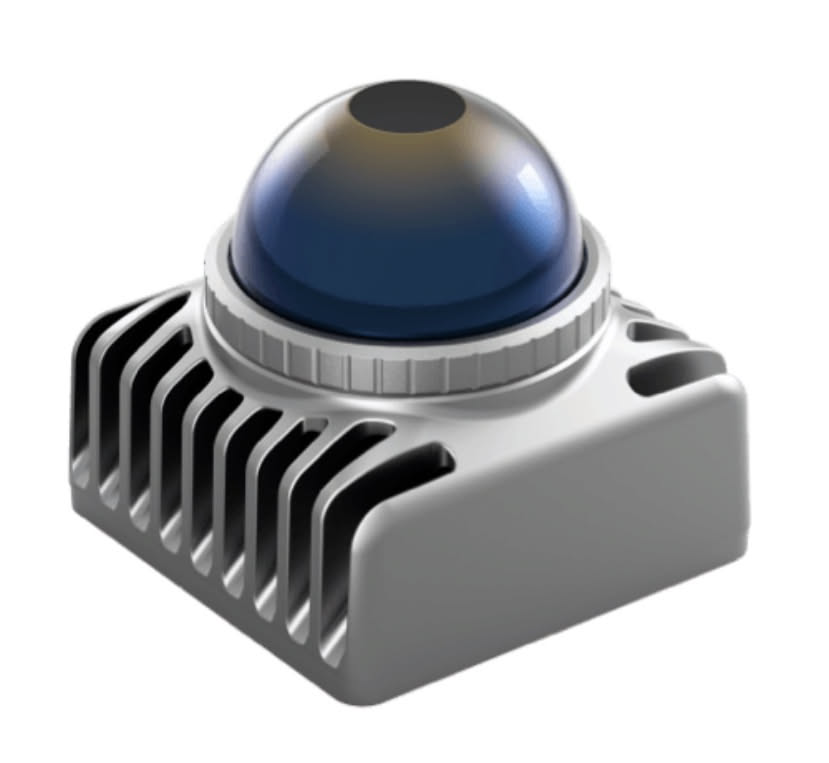
The primary sensor is a Livox Mid-360 (a 3D LiDAR with a built-in 6-axis IMU), handling both 3D shape capture of the surroundings and self-localization. A USB camera (Logitech C920) serves as a secondary sensor, used for visual-feature-based loop closure in mapping and for estimating distance to obstacles.
Control Computers
The chassis carries two separate compute resources. The main controller is a Raspberry Pi 5, handling edge-side processing — self-localization, safety supervision, sensor acquisition. Lower-level work (reading encoders, PWM motor control) is handled exclusively by an ESP32. See "How the ESP32 Firmware and Communication Protocol Work" for the details of that division of labor.
Power System
Power comes from a general-purpose 18 V battery pack, the same kind used with power tools, rather than a newly sourced dedicated battery — using a general-purpose standard simplifies sourcing spares and handling charging. The 18 V can't be used directly, so a DC-DC converter steps it down to 12 V (for the motors and motor driver) and 5 V (for the Raspberry Pi 5) separately.
Battery voltage monitoring is designed to run through the ESP32's ADC input, but feeding 18 V into it directly would destroy the pin (rated for 3.3 V). So a voltage divider drops the level first, analogSetPinAttenuation is set to match the divider, and the whole chain is calibrated against a real measurement. Running a driving test before this divider circuit was actually wired exposed exactly the failure mode you'd expect: the ADC input pin (GPIO39) sat floating, picked up motor-drive noise, and returned nonsense readings of 5–13 V. The battery-monitor node treated that fake reading as a dangerous voltage and fired an emergency stop mid-drive — a real incident, not a hypothetical one. The fix was to send a sentinel value meaning "not yet measured" over telemetry while the divider is unwired, with the monitor node treating that value as an invalid sample rather than a real one. Don't treat "the voltage can't be read" as "a dangerous voltage was read" — simple in hindsight, but easy to miss until it bites.
The Raspberry Pi 5's own power supply has caused real problems too. During driving tests it rebooted unexpectedly, for no immediately obvious reason, on two separate occasions — one of which happened mid-build and corrupted the install artifacts, sending a dependent service into a repeated startup-failure loop. The Pi 5 exposes a hardware flag for detecting undervoltage, and checking that flag is now a standing step in the bring-up procedure: if it's set, physical inspection of the power supply and wiring comes first, as a gate condition before any further autonomy testing.
Bring-Up and Calibration Procedure
Assembling the hardware isn't the finish line — the upper-level software can only handle it correctly once the encoder and motor-drive characteristics have been measured and calibrated. Time with the physical hardware is limited, so the procedure is kept as a single checklist to avoid backtracking, worked through top to bottom with a strict "meet the pass condition before moving on" rule.
Encoder Wiring and Polarity Check
Encoder signal lines need to avoid the ESP32's input-only pins (GPIOs with no internal pull-up). One instance of wiring into an input-only pin without noticing led to an unstable signal from the missing pull-up, later fixed by rewiring. Polarity is checked by turning one wheel forward by hand and visually confirming the tick count increases in the positive direction; if it's reversed, the sign is flipped in software.
Measuring Pulses Per Revolution (PPR)
The encoder's theoretical resolution (gear ratio × raw encoder resolution × multiplication factor) is affected by real mechanical backlash and gear play, so one wheel is turned by hand for exactly 10 revolutions while accumulating the tick count, and that measured value is what actually goes into the software configuration. This measurement connects to the low-speed count-cancellation problem covered in "How Safe Velocity Control Works" — the hand-turned measurement is used with the understanding that it's only a lower bound on the true value.
Calibrating Speed Command to PWM Duty Cycle
With the chassis lifted (or on a stand that lets the wheels spin freely), a known speed command (mm/s) is sent and compared against the actual speed measured back from the encoder, linearly correcting the conversion factor from speed command to PWM duty cycle. This is checked at several points across low, medium, and high speed, and the dead-band range — where the motor doesn't actually turn at low commanded speeds — is also mapped and reflected in software.
Measuring the Chassis Dimensions
The distance between the left and right wheels' contact points, the tires' actual measured diameter (the nominal value shifts under load and wear), sensor mounting angles — any dimension that directly affects driving is measured and fed back in. Skipping this measurement was, for a long stretch, one of the things blocking the first successful autonomous run described later (see "How Mapping and Autonomous Navigation Work" for details).
Concretely: the rear overhang was configured as 0.16 m while the measured value was 0.30 m, and the rotation sweep radius needed for in-place turning was configured as 0.22 m against a measured 0.327 m. Both were "unmeasured" provisional values that kept getting used as-is in production safety judgments, and it took the actual measurement to reveal how much collision-detection margin was being missed.
A Gotcha When Flashing Firmware
Flashing the ESP32 uses esptool, but the version installed through the package manager lacks the built-in fast-flashing mode (stub), so the --no-stub option has to be added explicitly. Trying the standard flashing steps without noticing this difference led to a failed flash.
A Mismatch Between the Real LiDAR and Its Model Number
At setup time, the discovery response over the network revealed that the LiDAR model actually delivered (Mid-360S) didn't match the one originally assumed (Mid-360). With the wrong model, the driver starts up against the matching config file and then silently stops (no error), which is easy to misdiagnose as a network fault. The model mismatch is recorded here as an oversight in hardware procurement.
Can rated encoder PPR directly convert counts to travel distance?
Include decoding multiplication, gearing, and wheel diameter. Verify scale and sign using a revolution or known travel distance.
Comments
Please log in to post a comment
No comments yet.