Design decisions
Division of Roles →
How the Distributed Processing Architecture Works
August 19, 2026Recorded status · Ongoing field testing
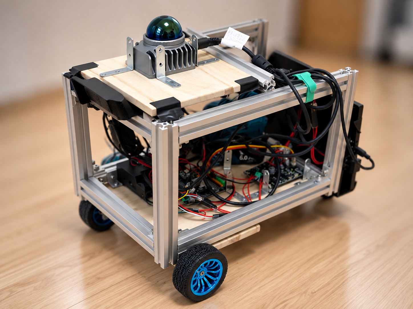
A differential-drive robot that uses LiDAR and a camera for self-localization, obstacle avoidance, and autonomous movement.
Design and build a differential-drive robot that performs self-localization, obstacle avoidance, and autonomous movement indoors using LiDAR and a camera. Processing is split across an edge unit and a PC to keep real-time performance within a limited wireless bandwidth budget. Safety is handled by a dual layer of control software and a physical kill switch, so a single failure never leads directly to an accident.
Design decisions
How the Distributed Processing Architecture Works
August 19, 2026Measurements and validation
How the Distributed Processing Architecture Works
August 19, 2026Failures and lessons
How Safe Velocity Control Works
August 13, 2026Figure 1 — The safety supervisor intervenes with top priority in both autonomous and manual modes. Sensor input is processed on the edge unit, and only decimated data is sent to the PC.
Can now be driven manually with a controller, and estimates its own position from wheel rotation counts.
Can now build a map of its surroundings automatically using LiDAR (a sensor that measures distance to nearby objects with a laser) and a camera.
Can now move automatically to a destination picked on the map, avoiding obstacles along the way.
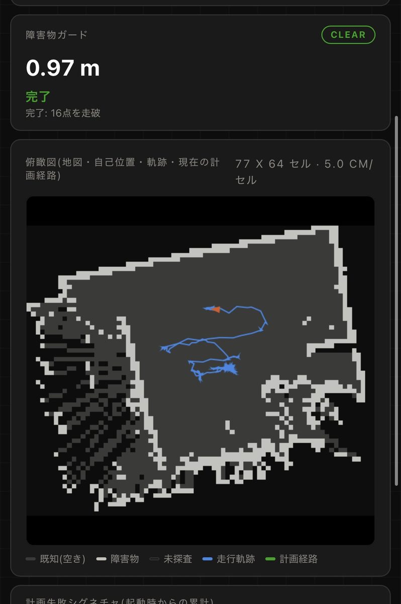
Automatically slows down and stops when approaching an obstacle, making collisions with walls or objects less likely (though not entirely preventable).
Battery level and sensor connection status can now be checked in real time from a browser.
If the control computer stops unexpectedly, manual control and the physical emergency stop button keep working independently.
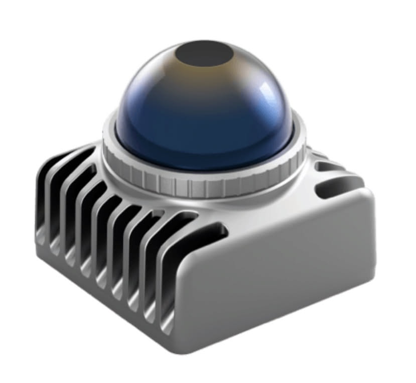
Equipment actually used in this project, with its role and constraints. Each entry is based on a research-log record. Prices and availability are not listed.
Livox
Logitech
Record: How the Hardware Is Put TogetherRecord: How Safe Velocity Control Works
Raspberry Pi
Espressif Systems
Cytron Technologies
Stage 0-1
Verified communication with the chassis, motor driver, and encoders, and achieved manual driving with odometry estimation. Laid the groundwork for every stage that followed.
Stage 2-3.5
Integrated the LiDAR and camera, achieved 2D map generation via SLAM, and then moved to high-precision self-localization using 3D LiDAR-Inertial Odometry.
Stage 4
Implemented goal-reaching with Nav2 and confirmed autonomous movement to a specified point, with a safe handover between manual and autonomous operation.
Stage 4.5
Migrated to a setup that keeps sensor acquisition and safety supervision on the edge unit while mapping and navigation run on the PC, preserving real-time performance under limited wireless bandwidth.
Stage 4.7-ongoing
Built out the obstacle guard, status dashboard, and physical e-stop, and continue to iterate through field testing and improvement.
The aluminum-frame chassis, differential drivetrain, a power system built on a power-tool battery, and the LiDAR/camera sensor setup.
July 25, 2026The serial protocol linking the upstream computer to the motor-control microcontroller, and the autonomous fail-safe that kicks in when communication drops.
August 19, 2026A distributed setup that offloads heavy processing to a PC while keeping drive control and safety supervision on the edge unit, and the decimation design that carries sensor data over limited wireless bandwidth.
July 31, 2026A self-localization design that switches between FAST-LIO and an EKF depending on whether LiDAR is present, and the drift accuracy measured on real runs.
August 6, 2026Building a 2D map on top of 3D LiDAR-derived odometry and driving to a goal autonomously with Nav2, plus a serious bug found along the way.
August 13, 2026The twist_mux pipeline that safely arbitrates between autonomous planning and manual commands, and the obstacle guard's asymmetric clamp that limits only the forward component.
August 25, 2026A read-only status dashboard built entirely on the edge unit using standard libraries, with no extra ROS package dependencies.