Contents — find the section you need
Two sources of speed commands — autonomous planning and manual operation — are safely consolidated into a single output, on top of which collisions with obstacles are mitigated. This article covers newbot's velocity-control pipeline at the implementation level.
The cmd_vel Arbitration Pipeline: Priority and Lock, Two Layers
Consolidating speed commands runs on two control axes with different characters.
Nav2 controller/behavior --(remap)--> /cmd_vel_nav
   --velocity_smoother--> /cmd_vel_smoothed
   --collision_monitor--> /cmd_vel_nav_safe ─┐
keyboard/procon teleop ------------> /cmd_vel_key ──┼─ twist_mux ─(cmd_vel_out=/cmd_vel)→ esp32_bridge
                                             │
                              /estop, /manual_override_active
Priority: keyboard(50) > navigation(10). A higher number wins, so while there's manual input, commands from autonomous planning are ignored. Lock: estop(255) > manual_override(100). A lock is a separate axis from priority — while active, it completely blocks any command that isn't from that source.
The important part is never wiring the raw /cmd_vel_nav directly into twist_mux. Nav2's output only reaches twist_mux after passing through velocity_smoother (smoothing acceleration/deceleration) and collision_monitor (checking against nearby obstacles). In fact, this exact path was once misconfigured — a bug that entirely bypassed collision_monitor's safety check — and it was caught and fixed before deployment on real hardware.
There's another trap that was hit here too: a default value for a message type changed in some ROS2 release without anyone noticing, and the message type mismatch between twist_mux and Nav2/the drivetrain meant the connection never actually formed at all. ROS2 won't establish a pub/sub connection if the types don't match, so commands were being generated but had never once actually reached the motors. Manual driving used a separate path (the ESP32 processes controller input directly) and was unaffected, which is exactly what delayed noticing the problem — everything looked like it was working.
The Obstacle Guard: An Asymmetric Clamp That Stops Only the Forward Component
Nav2's collision_monitor only has effect on the autonomous-planning (cmd_vel) path. During manual operation, the ESP32 converts controller input directly into motor drive, so this safety mechanism has no way to constrain manual driving by design (that's the flip side of the design choice to keep the manual path independent of the upstream computer, not a flaw).
So a separate, mode-independent channel that applies equally to both the autonomous and manual paths was added. A single value — "forward speed limit" — is sent to the ESP32 continuously, regardless of control mode.
LiDAR (raw point cloud) ─┐
                 ├→ obstacle_guard ─/forward_speed_limit→ esp32_bridge ─"L,<mm_s>"→ ESP32
Camera (obstacle distance estimate)─┘        (takes the minimum of the two sensors' estimates)
Inside the ESP32 firmware, the received left-wheel speed l and right-wheel speed r command is decomposed into a forward component v and a turning component w.
This is exactly the differential-drive kinematics covered in the earlier navigation article (the conversion between translational/rotational speed and left/right wheel speed) — the cap is applied only to the forward component v, and the left/right wheel speeds are recomposed afterward. Turning and reversing are never limited. The reasoning: getting stuck immobile right in front of an obstacle is judged more dangerous than retaining some forward speed — the design always leaves a way out.
The staged threshold control is as follows.
| State | Distance threshold | Forward limit | Turn / reverse |
|---|---|---|---|
| CLEAR | over 1.0 m | unlimited | allowed |
| SLOW | ≤ 1.0 m | 0.12 m/s | allowed |
| BLOCK | ≤ 0.5 m | 0 (forward forbidden) | allowed |
| CRITICAL | ≤ 0.3 m | 0 (immediate stop) | allowed |
| SENSOR_LOST | all sensors down | SLOW-equivalent by default | allowed |
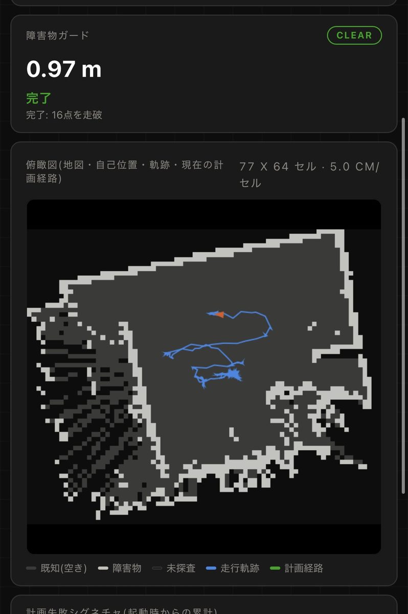
The status dashboard during an actual drive. The obstacle guard shows a CLEAR judgment at a detection distance of 0.97 m, with a top-down view (known open space, obstacles, and driving trail) updating in real time below it.
The threshold's activation and release are deliberately asymmetric (a default hysteresis of 0.1 m). Activation happens the instant the distance is detected (erring toward safety); release waits until the robot is a further 0.1 m past the threshold. A symmetric hysteresis would flip the limit on and off (chattering) every time the robot lingers near the boundary — this asymmetric design prevents that. The cap is applied to both the target speed and the speed actually applied, closing off a loophole where, at close range, "the acceleration cap alone isn't enough to actually stop in time."
A Dual Fail-Safe
The Pi 5 keeps sending the forward-limit command to the ESP32 every 40 ms, and if that command goes silent for 1 second, the ESP32 autonomously falls back to a fixed low-speed cap — neither reverting to unlimited nor dropping to a full 0. It's a compromise that avoids breaking the manual path's independence: even if the upstream computer crashes, the robot can still be driven clear manually.
Real Collisions, and the Process of Investigating Them
The obstacle guard wasn't finished purely on paper. In mid-August 2026, field testing produced several front, side, and rear collisions, and each one triggered a fresh investigation and design revision. What follows is that investigation process, wrong initial hypotheses included.
The First Hypothesis: A Geometric Blind Spot from LiDAR's Vertical FOV
When the first collision happened, the cause was assumed to be a geometric blind spot created by the LiDAR's (Livox Mid-360) vertical field of view (-7° to +52°). Working backward from the mount height, at a distance of 0.3 m only objects 18.9 cm or taller could be detected, and the minimum detectable height rises the closer the distance gets. Going purely by that theory, the front detection limit should have worked out to around 0.858 m.
The Discrepancy That Measurement Revealed
But when the detection limit was actually measured separately at the front, sides, and rear, the results clearly diverged from what the geometric model predicted. The front matched the theory at around 0.858 m, but the sides (60–90°) came in at 0.389 m and the rear at 0.36 m — both far shorter than the vertical-FOV calculation alone could explain. If the cause were purely the geometry of the vertical FOV, the relationship should hold roughly constant regardless of direction. This discrepancy pointed to a more accurate diagnosis: the root cause was likely not a geometric FOV problem at all, but the LiDAR's mounting orientation or occlusion by the chassis itself. Even without being able to fully pin down the cause, the approach taken was to first lay out everything that was a confirmed fact, then narrow in on the highest-confidence fixes from there.
Laying Out the Confirmed Facts
To keep moving even without a fully identified cause, confirmed facts alone were listed out, numbered, and used to set priorities for what to fix. The main ones:
- LiDAR point counts drop to zero within 0.858 m at the front, 0.389 m to the sides (60–90°), and 0.36 m at the rear (measured, not assumed or estimated)
- The rotation clamp (a variable called
rotationLimitMmS) was only ever declared, and was never actually referenced anywhere in the code. In other words, the design documentation's own claim of "turning is limited" didn't match the implementation at all - The rear direction was entirely excluded from the speed clamp — the firmware's
applyForwardLimitnever applied any clamp at all when v < 0 (reversing). This turned out to be the direct cause of an actual rear collision, triggered by Nav2's automatic recovery behavior (BackUp) - Distance estimation derived from the map (an already-built SLAM map) was confirmed to work reliably down to 0.020 m — usable as an alternative distance source that doesn't depend solely on the raw LiDAR point cloud
- Enabling the camera spikes CPU usage to around 75%, dropping self-localization's (FAST-LIO) update rate from 10 Hz to 0.5 Hz — adding sensors doesn't automatically mean more safety; there's a trade-off against processing load
- One case was confirmed where every direction was blocked simultaneously, leaving the robot stuck (deadlocked) for more than 45 seconds
- The whole series of collisions happened at a speed of 0.12 m/s, and not one of them caused any physical damage
A Shift in Design Philosophy: "Naive Concept, Expert Execution"
Working from these facts, the safety-design policy itself was overhauled. The implementation up to that point had layered on individually reasonable-looking tricks — time latches, direction-specific exclusion zones, remembered map data, taking the minimum across multiple sensors — and the overall conclusion was that trying to be "too clever" had itself become the breeding ground for the bugs. That led to a shift toward a policy where the concept itself can stay simple, but the execution doesn't compromise — "naive concept, expert execution."
Five operating principles were set under this policy:
- Fail-safe as the default — when in doubt, stopping is the default behavior
- Always leave room to creep out — never a full stop; always leave some direction the robot can still move, even at low speed
- Confirm not just "published" but "actually arrived and took effect" — publishing to a topic and that publish actually changing motor behavior are two separate things that both need checking
- Set speed limits from measurement, not theory — work backward from the speed range where real collisions actually happened, not a theoretical value
- Keep regression tests built on the numbers from real incidents (
safety_math.py) — to pin down a bug once it's fixed so it can't come back
Reorganizing into a 4-Layer Architecture
This architecture is made up of the following four layers.
[Sensing layer]   LiDAR mounting angle / orientation
[Execution layer] Speed clamp inside the ESP32 (left / right / reverse, each independent)
[Policy layer]    obstacle_guard (handles only the forward cap; no complex exception handling)
[Planning layer]  Nav2 / coverage_mission (path planning, coverage exploration)
At the sensing layer, one option under consideration is tilting the LiDAR 15–25 degrees downward from the body. The plan is to calculate, for each candidate mounting angle, the distance at which the floor first becomes visible, and choose based on that — raising sensitivity to low obstacles at close range without adding any extra electronic processing.
A Physical Bumper as the Last Line of Defense
Working from the assumption that even trusting every software layer above still won't get the risk to zero, a physical bumper switch is being planned as an independent layer that depends on none of software, network, or the upstream computer. The plan wires a normally-closed contact directly into an ESP32 GPIO interrupt, aiming for a design that can stop the motors even if the Pi 5 and every ROS2 node are completely down. It's mapped out as a staged rollout: the current 3-layer software defense, then adding the physical bumper, then integrated verification.
A Structural Problem: The Guard and Nav2 Don't Know About Each Other
Adding the obstacle guard cut down on contact incidents, but it also surfaced a different kind of deadlock. The guard independently clamps forward, rotation, and reverse, but Nav2 has no idea any of that clamping exists. Nav2 assumes the robot moves however it commanded, so when it doesn't, Nav2 reads that as its own failure — Failed to make progress — and reaches for a recovery behavior instead. Measured in practice: that "no progress" condition fired 12 times, while the recovery behavior meant to address it — turning in place — actually ran 0 times. In other words, recovery behaviors were being chosen without Nav2's picture of the situation ever lining up with what was actually stopping the robot.
What makes it worse is that the guard only exposes the resulting limit value, not the reasoning behind it. A "forward speed limit = 0" value on its own gives upstream no way to tell whether it's because there's a wall 0.15 m ahead, or for some other reason entirely. That's the core weakness of this structure — the information isn't shaped in a way anything upstream can actually reason with. As a first response, a topic was added that detects and exposes the state where every direction is blocked at once, but that's meant purely for a human to notice — it doesn't change Nav2's decision logic at all. Two more substantial fixes are under consideration: publishing clearance itself (front/rear/all-around distance) so upstream can judge which way it can retreat, or reflecting the guard's clamp state directly into Nav2's costmap so the planner never picks a blocked direction in the first place (implementable as a custom costmap layer). The latter is the real fix.
Three Protection Layers, Each Running on a Different Set of Assumptions
The mechanism protecting the robot from obstacles isn't actually one layer — it's three. The obstacle guard on the edge unit watches the raw point cloud directly; Nav2's collision_monitor on the PC watches /scan; and the costmap, also on the PC, watches the same /scan plus its own footprint configuration. These three layers each run on a different data source and an independently maintained geometry definition, and nothing exists to notice if those definitions ever drift apart. In fact, the chassis rear-overhang error covered earlier in this article was exactly the kind of inconsistency that wouldn't have surfaced by looking at only one of these three in isolation.
On top of that, the obstacle guard running only on the edge unit is a deliberate design choice (so protection stays alive even if the PC or the network goes down), and that choice is correct on its own terms. But flip it around: disable this guard for any reason, and edge-side protection drops to zero. During the experiment where the guard was removed, the PC-side collision_monitor was still reacting frequently — but that's PC-side protection only, and it has the same limitation noted earlier: it disappears the instant Wi-Fi drops.
The Limit: This Is "Mitigation," Not a "Guarantee"
The obstacle guard reduces the likelihood of a collision, but it can't bring it to zero. LiDAR has blind spots directly above, directly below, and at close range near the floor; the camera has a complete blind spot outside its horizontal field of view (directly to the side, and behind). Monocular camera distance estimation depends on the assumption that the floor is a flat plane, and produces error on a step or a reflective floor. There's a delay between detection and braking, and that delay eats into the safety margin more the faster the robot goes. Which is exactly why a physical kill switch that cuts motor power directly, independent of any software safety mechanism, is a requirement, not an option.
Does an upstream obstacle guard guarantee a stop after link failure?
The downstream controller needs command-expiry handling. Test generating a stop request separately from stopping the motors.
Comments
Please log in to post a comment
No comments yet.