Contents — find the section you need
The upstream computer handling autonomous planning and decisions (a Raspberry Pi 5) and the low-level control that actually drives the motors (an ESP32) are kept cleanly separated by role. That way, even if the upstream side crashes during some heavy computation or loses communication, the last line of defense for driving the motors keeps running independently.
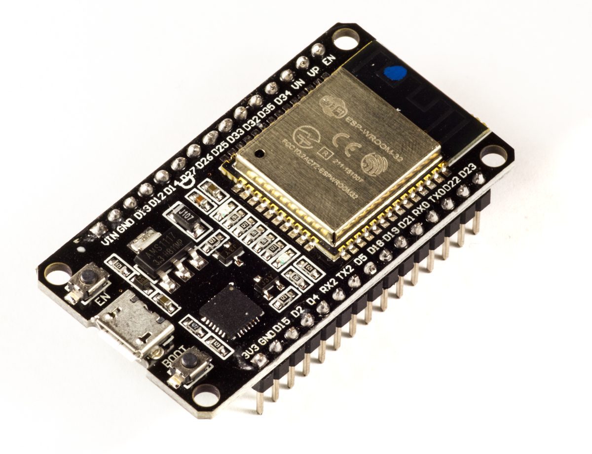
An example ESP32 development board (a generic reference photo, not the actual unit). newbot uses a Freenove ESP32 development board.
Image: Edwiyanto, Wikimedia Commons (CC BY-SA 4.0)

Division of Labor: Separating High-Level Decisions from Real-Time Control
The Raspberry Pi 5 handles the computationally heavy work — self-localization, mapping, path planning. The ESP32 is dedicated to reading encoders and PWM motor control, work that demands low-latency, real-time performance. The two talk over USB serial, at 115200 bps, using a newline-delimited text protocol.
The Serial Protocol: Commands Every 40 ms
Every 40 ms, the Pi 5 sends the following commands to the ESP32:
V,<left wheel mm/s>,<right wheel mm/s>— speed command (only takes effect in autonomous mode)X0/X1— release/trigger emergency stop (sent every cycle; while triggered, motors are forced to stop regardless of mode)L,<forward speed limit mm/s>— forward speed cap (sent every cycle; -1 means unlimited, 0 means forward motion forbidden)P— request to re-pair the controller (erases the Bluetooth key and rescans)
Sending the forward speed cap before the speed command closes off a loophole where, within the same cycle, a new speed command could otherwise slip through still paired with the old cap.
Every 40 ms in the other direction, the ESP32 reports wheel rotation counts, elapsed time, the current operating mode, battery voltage, and controller connection status back to the Pi 5.
A Dual Watchdog
Both the ESP32 side and the Pi 5 side carry their own safe-side fallback for when communication drops. The ESP32 side falls back to the safe side autonomously if it detects no command for 300 ms in autonomous mode, or 500 ms in manual mode. The Pi 5 side detects the other side going unresponsive after 500 ms. Having both sides carry this — not just one — is a deliberate design choice: safety is never left resting on a single monitoring mechanism.
Pairing the Controller
Pairing the manual-control controller (a Nintendo Switch Pro Controller, via Bluepad32) is implemented as the ESP32 firmware's responsibility. Since it automatically waits and scans by default whenever nothing is connected, the operational flow stays simple: the Pi 5 boots, communication is established, and the system is already sitting in a pairing-ready state.
The BP32.setup() Trap That Blocked Real Pairing
Bluepad32's sample code makes it look like calling BP32.setup() alone is enough for a controller to connect, but on the real hardware, new pairing never went through. The cause: BP32.setup() doesn't accept new Bluetooth connections by default, and BP32.enableNewBluetoothConnections(true) needs to be called explicitly. On top of that, a controller that had once failed to pair would keep holding onto its old Bluetooth key on the Pro Controller side and get rejected on retry — so sending the P command over serial now calls forgetBluetoothKeys() to erase the key and let pairing start fresh (this is the role of the P command listed above). A "re-pair" button was also added on the dashboard, which sends this same command to the ESP32 via a /procon_pairing_reset service.
There's a hardware constraint on the Bluetooth side too. The Nintendo Switch Pro Controller communicates over Bluetooth Classic (BR/EDR), and can't connect to a chip that only supports BLE (Bluetooth Low Energy). That limits the usable ESP32 modules to the plain variants that include BR/EDR (like the WROOM-32), and rules out the ESP32-S3 or ESP32-C3, which only support BLE.
The actual pairing procedure is:
- Boot the ESP32 and confirm
BP32 setup complete, waiting for controller...in the serial log - Hold the Pro Controller's sync button (the small button next to the minus button on top) to blink its LED and enter pairing mode
- Success is a connection-complete message in the serial log, like
CONTROLLER CONNECTED, Model: ... - If connection fails, send the
Pcommand to erase the key and retry
Flashing the Firmware
esptool.py flashes the built binary at 921600 baud in dio flash mode. During development, the serial monitor is checked right after flashing to confirm the pairing-complete message above shows up, and that 40 ms telemetry is coming through steadily.
Real-World Gotchas Logged in CLAUDE.md
On the way to putting this on real hardware, the following firmware-related problems came up and had to be dealt with.
deploy.shwasn't syncing the firmware:deploy.shon the Pi 5 side syncs the ROS2 packages, but the.inofile flashed onto the ESP32 was never part of what got synced to the repo. That meant the firmware actually running on the Pi 5 (with e-stop, Bluepad32, and 4x encoder multiplication) had drifted from what was in the repository for a long stretch without anyone noticing. What was still sitting in the repo when this was discovered was a minimal 161-line version with no safety mechanisms at all — a large gap in both line count and functionality from what was actually flashed. The root cause was assuming the deploy script's scope started and ended with "ROS2 nodes only" — the lesson is that anything flashed onto hardware needs to be in scope for syncing too.- A speed-command overwrite bug in MANUAL mode: during manual operation (MANUAL mode), a speed command from the autonomous system (the
Vcommand) — which should have been ignored — was overwriting motor output. The initial investigation traced the code in isolation without reproducing the actual node topology (the real wiring of twist_mux and esp32_bridge), and the first hypothesis missed the mark entirely. It only became clear once the traffic between the actually-running nodes was observed directly withros2 topic echo, revealing the command was flowing through a different path than assumed. Don't narrow down a cause on hypothesis alone — observe the system as it's actually running is the lesson that stuck from this one. - A fixed telemetry column count: the telemetry line the ESP32 sends the Pi 5 is parsed upstream on the assumption that the column count (currently 6) is fixed. Casually adding a debug column on the firmware side makes the parser silently misbehave (values shift with no exception raised), so the sending and receiving sides are always changed together whenever a column is added or removed.
The Clamp That Was "Declared but Never Actually Wired In"
Separately from the forward-speed cap (the L command) sent from upstream, an R command for capping rotation speed was added on 2026-08-13. But the implementation only went as far as receiving the value and assigning it to a variable — the function that would actually apply it to motor output was never written. In other words, rotationLimitMmS was declared and assigned, but referenced nowhere else in the code, while still being treated as production guard logic.
In that state, a contact incident occurred: the chassis side hit an obstacle during one of Nav2's automatic recovery moves — a Spin, which turns in place to break out of a stuck condition. The rotation guard was supposed to be implemented, but rotation was in fact unbounded, and that was the direct cause. The log shows Turning 1.57 for spin behavior running for close to 12 seconds, but the rotation component was passing through unclamped the whole time, meaning the wheels likely weren't actually turning as commanded. This incident left a clear lesson: there's an easy gap between "it's held as a config value" and "it actually reaches the motor" — an implementation gap, not a logic error.
The fixed applyRotationLimit() decomposes left/right wheel speeds l, r into a forward component v and a rotation component w, clamps only w, and recomposes. It mirrors applyForwardLimit() on the forward side.
void applyRotationLimit(float &l, float &r) {
  float limit = rotationLimitMmS;
  if (millis() - lastLimitMillis > LIMIT_TIMEOUT_MS) {
    limit = LIMIT_FAILSAFE_MM_S;   // fall back to a low-speed fail-safe if the command has gone stale
  }
  if (limit < 0.0f) return;        // unlimited
  if (allAxesBlocked()) {
    limit = ROTATION_ESCAPE_CREEP_MM_S;  // leave an escape creep if every axis is blocked
  }
  float v = (l + r) / 2.0f;
  float w = (r - l) / 2.0f;
  if (w > limit) w = limit;
  else if (w < -limit) w = -limit;
  else return;
  l = v - w;
  r = v + w;
}
Then on 2026-08-14, a fourth contact incident happened, this time a rear collision. Forward and rotation clamps were both implemented by that point, but the reverse direction (v < 0) had no clamp at all, and Nav2's BackUp recovery behavior was the trigger. There's an ironic feedback loop confirmed here too: the harder forward and rotation get clamped, the more Nav2 concludes it "can't move forward" and reaches for BackUp instead. The fix was a new applyReverseLimit() that clamps the reverse component under the same framework.
If forward, rotation, and reverse are all clamped to zero at once, the robot is fully immobilized and can't move in any direction. That actually happened — the robot sat stuck for more than 45 seconds on one occasion, and had to be rescued by pushing it by hand. In response, allAxesBlocked() was added to detect the fully-blocked state, and when it fires, a low-speed creep (just enough to escape) is left available in the reverse direction. A matching creep for rotation (ROTATION_ESCAPE_CREEP_MM_S) was added later, after confirming a case where Nav2 chose a Spin recovery but the rotation cap was still at zero, so no actual rotation happened at all. The rotation creep is set somewhat lower than the reverse one, on the reasoning that rotation needs more clearance margin than reverse does, since the corners of the chassis sweep outward as it turns.
The Fail-Safe Value When the L Command Goes Stale
If the L/R commands from upstream go silent for longer than LIMIT_TIMEOUT_MS (1000 ms), none of the forward, rotation, or reverse limits reverts to unlimited — instead, all of them autonomously fall back to a fixed low-speed cap, LIMIT_FAILSAFE_MM_S (120 mm/s). It's a middle ground: it accounts for the possibility that the upstream computer's obstacle monitoring has died, while still leaving enough room for a human to drive the robot clear manually.
A Last Line of Defense Still Under Consideration: A Physical Bumper
Working from the premise that even trusting every one of the software layers above won't get collisions to exactly zero, a physical bumper switch is under consideration as an independent layer that depends on none of the Pi 5, ROS2, or the LiDAR being alive. The design wires a normally-closed (NC) microswitch straight into an ESP32 GPIO interrupt, combined with a pull-up and hardware debouncing (an RC circuit). NC contacts are chosen so that even a broken wire fails toward the "pressed" state — a fail-safe by construction. The firmware side would latch a flag on the interrupt, then clamp forward motion to zero while still allowing a reverse creep. Release would require either backing away physically or an explicit command. None of this depends on the Pi, ROS2, or the LiDAR staying alive, which lines up with the existing design principle that the manual-control path shouldn't depend on the upstream computer.
Should the last velocity command persist after communication loss?
Follow the robot's command-expiry policy. Test both timeout detection and the actual output-stop behavior.
Comments
Please log in to post a comment
No comments yet.