Can now be driven manually with a controller, and estimates its own position from wheel rotation counts.
Abbildungen, Code und weiterführende Projektnotizen verwenden teilweise das englische Original.
← Zurück · Projekte
PROJECT / NEWBOT
Autonomer Indoor-Roboter
Design and build a differential-drive robot that performs self-localization, obstacle avoidance, and autonomous movement indoors using LiDAR and a camera. Processing is split across an edge unit and a PC to keep real-time performance within a limited wireless bandwidth budget. Safety is handled by a dual layer of control software and a physical kill switch, so a single failure never leads directly to an accident.
Entwicklung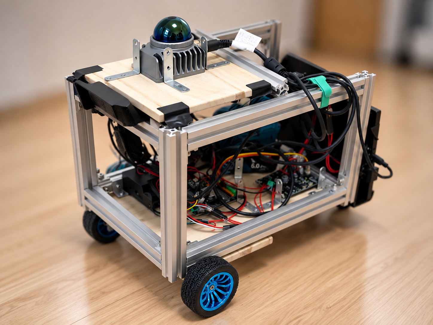
Systemaufbau
SYSTEMFigure 1 — The safety supervisor intervenes with top priority in both autonomous and manual modes. Sensor input is processed on the edge unit, and only decimated data is sent to the PC.
Umgesetzte Funktionen
6 capabilitiesCan now build a map of its surroundings automatically using LiDAR (a sensor that measures distance to nearby objects with a laser) and a camera.
Can now move automatically to a destination picked on the map, avoiding obstacles along the way.
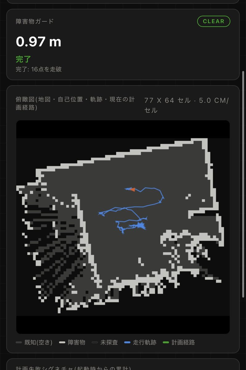
Automatically slows down and stops when approaching an obstacle, making collisions with walls or objects less likely (though not entirely preventable).
Battery level and sensor connection status can now be checked in real time from a browser.
If the control computer stops unexpectedly, manual control and the physical emergency stop button keep working independently.
Technologien und Werkzeuge
Chassis / Hardware
Aluminum frame (3-tier)2x differential-drive geared motorsCytron MDD10A motor driver
Sensors
Livox Mid-360 (LiDAR + IMU)Logitech C920 (USB camera)
Control Computers
Raspberry Pi 5ESP32
Software Stack
ROS2 JazzyUbuntu 24.04
Self-Localization
FAST-LIOrobot_localization (EKF)
Mapping / Autonomous Navigation
slam_toolboxNav2RTAB-Map
Custom Implementation
twist_mux arbitrationsafety supervisor nodeobstacle guardweb dashboard
Equipment
8 itemsEquipment actually used in this project, with its role and constraints. Each entry is based on a research-log record. Prices and availability are not listed.
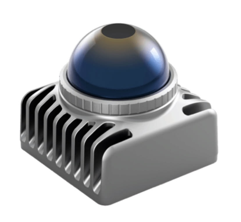
Livox Mid-360S
Used in this buildLivox
- Role
- Primary sensor. A 3D LiDAR with a built-in 6-axis IMU, used both to capture the 3D surroundings and for self-localization.
- Limitations & notes
- Ordered as a Mid-360, but the delivered unit was a Mid-360S (found from the network discovery response). With a configuration for the wrong model, the driver stops without reporting an error.
Logitech C920
Used in this buildLogitech
- Role
- Secondary sensor (USB camera), used for visual loop closure in mapping and for distance estimation to obstacles.
- Limitations & notes
- Enabling it raised CPU usage to about 75% and dropped the FAST-LIO localization update rate from 10 Hz to 0.5 Hz (measured).
Raspberry Pi 5
Used in this buildRaspberry Pi
- Role
- Main onboard computer, running edge-side processing such as localization, safety supervision and sensor acquisition.
- Limitations & notes
- It rebooted unexpectedly twice during driving tests, cause unknown. Checking its undervoltage flag is now a precondition for autonomous-driving tests.
ESP32
Used in this buildEspressif Systems
- Role
- Microcontroller dedicated to reading the encoders and generating motor PWM.
- Limitations & notes
- GPIO34–39 are input-only with no internal pull-up, and INPUT_PULLUP is silently ignored; the encoder lines were rewired to GPIO18/19. The exact board model is not recorded.
Cytron MDD10A
Used in this buildCytron Technologies
- Role
- Two-channel motor driver that turns speed commands into PWM to drive the left and right motors.
- Limitations & notes
- Because the motors are mounted as mirror images, the right motor's DIR logic is inverted in software.
Encoder gear motors (12 V, 100 RPM, 65 mm wheels) × 2
Used in this build- Role
- Left and right wheels of the two-wheel differential drive, with one caster for turning and stability.
- Limitations & notes
- Pulses per revolution are measured by turning each wheel ten times by hand rather than taken from nominal values. Manufacturer and model are not recorded.
18 V power-tool battery pack
Used in this build- Role
- Main power source, stepped down by DC-DC converters to 12 V (motor side) and 5 V (Raspberry Pi 5).
- Why
- A common standard rather than a dedicated pack makes spares and charging simpler.
- Limitations & notes
- Voltage monitoring with the ESP32 ADC requires a divider and calibration; running without the divider wired made noise read as voltage and triggered an emergency stop. The brand is not recorded.
Three-tier aluminium frame (approx. 300 × 200 × 200 mm)
Used in this build- Role
- Chassis, with paulownia shelves on each tier separating drive, computing and sensors.
- Why
- Physical separation keeps wiring and heat management easy to follow.
Hardware
Lernwege nach Fachgebiet
Stage 0-1
Foundation
Verified communication with the chassis, motor driver, and encoders, and achieved manual driving with odometry estimation. Laid the groundwork for every stage that followed.
Stage 2-3.5
Sensor Integration and SLAM
Integrated the LiDAR and camera, achieved 2D map generation via SLAM, and then moved to high-precision self-localization using 3D LiDAR-Inertial Odometry.
Stage 4
Achieving Autonomous Navigation
Implemented goal-reaching with Nav2 and confirmed autonomous movement to a specified point, with a safe handover between manual and autonomous operation.
Stage 4.5
Moving to a Distributed Architecture
Migrated to a setup that keeps sensor acquisition and safety supervision on the edge unit while mapping and navigation run on the PC, preserving real-time performance under limited wireless bandwidth.
Stage 4.7-ongoing
Hardening Safety and Field Testing
Built out the obstacle guard, status dashboard, and physical e-stop, and continue to iterate through field testing and improvement.