Contents — find the section you need
Background and reading guide
Background Units used in specifications, such as voltage, current, distance and time.
Fundamentals · Explanations of principles, structure and trade-offs.
A force sensor measures the force and torque acting on a robot arm's wrist or joints as a vector. It underlies safety functions that let a collaborative robot detect a dangerous contact force and stop, as well as assembly tasks that demand careful force control, such as inserting a part into a hole. A tactile sensor measures the contact pressure and slip distributed across a surface — a fingertip or a palm — as a field. It is what lets a hand grip an egg without crushing it. Both share the same underlying principle: converting mechanical deformation into an electrical signal. But a force sensor aggregates the total force acting on an entire structure into a single 6-axis vector, while a tactile sensor captures the pressure distribution across a contact surface as an array. The two are complementary, together forming the "sense of the arm" and the "sense of the fingertips" in collaborative robots and humanoids.
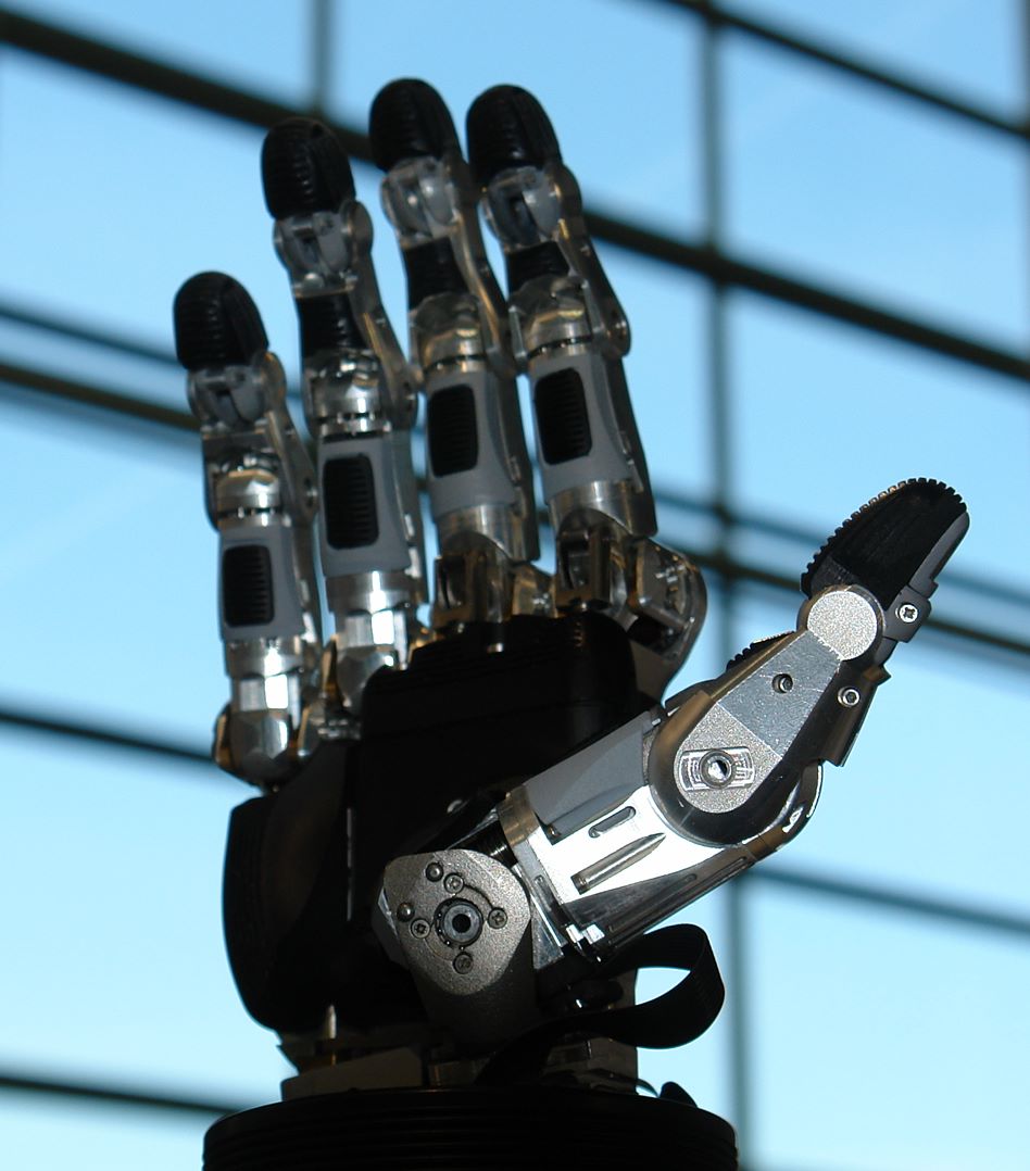 Schunk SVH (servo-electric five-finger gripping hand, Hannover Messe 2016)
Image: Robotic Hand at Hannover Messe 2016 (NearEMPTiness, CC BY-SA 4.0), Wikimedia Commons. An example of a commercial five-finger hand with electronics built into the wrist that mimics human hand motion — not one of the standalone force/tactile sensors compared in this article, but a typical example of a system these sensors get integrated into.

Principle: force sensors turn "strain" into an electrical signal
At the core of a force sensor is the strain gauge. A thin metal foil or a semiconductor element is bonded to the surface of an elastic body (the flexure element), and when a force is applied and the flexure element deforms slightly, the bonded conductor stretches and compresses along with it. As a metal conductor stretches, its cross-sectional area shrinks and its length increases, so its electrical resistance rises in proportion — the ratio between this fractional resistance change and the strain (fractional elongation) is called the Gauge Factor (GF).
Here \epsilon = \Delta L / L is the strain (fractional elongation), and \Delta R / R is the fractional change in resistance. A typical metal-foil gauge has a GF of only about 2, whereas a semiconductor (silicon) gauge exploits the "piezoresistive effect," in which stress directly changes the mobility of charge carriers, reaching a GF of roughly 70 to 200 — for the same amount of strain, this yields an output voltage tens to over 100 times larger than a metal-foil gauge, which is why semiconductor gauges dominate in small, high-precision sensors.
Because the resistance change from strain is tiny (well under 0.1%), directly measuring a single resistor's change is impractical. Real sensors instead wire four resistors into a diamond-shaped Wheatstone bridge circuit and detect strain as the potential difference across the diagonal. Depending on how many of the bridge's four legs carry an actual strain gauge — one-gauge, two-gauge, or full-bridge configurations — sensitivity and temperature compensation characteristics change; most precision force sensors use a full-bridge configuration (a gauge on all four legs) to cancel out temperature drift.
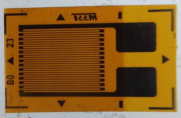 Strain gauge (before mounting)
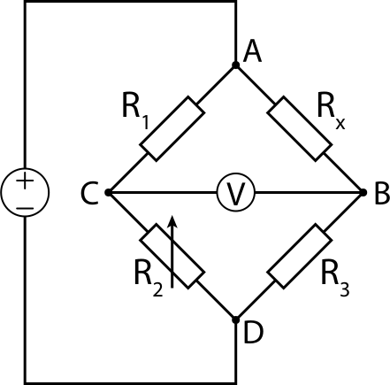 Wheatstone bridge circuit
Images: Strain gauge - (Cristian V., CC BY 4.0) / Wheatstone Bridge (jjbeard, public domain), both Wikimedia Commons.


The 6-axis F/T sensor mounted on a robot arm's wrist cannot get by with a single strain gauge measuring one direction. It must separate and measure all six components — force (Fx, Fy, Fz) and torque (Tx, Ty, Tz) — so the flexure element is machined into a radial beam structure called a "Maltese cross," with multiple strain gauges placed on each beam. This layout is mechanically engineered so that when a single force or torque component is applied, only a specific combination of beams deforms selectively. The raw strain readings from multiple channels are then linearly transformed by a 6×N calibration matrix C (where N is the number of gauges) to separate out the six force/torque components.
The calibration matrix C is determined at the factory through a "calibration test," in which known weights and torque wrenches are applied to the actual flexure element while recording each gauge's output. This calibration process is exactly where specialist makers like ATI and Bota Systems hold their edge: beyond the mechanical design of the flexure element itself, product differentiation comes down to calibration precision — keeping each of the six axes' error (crosstalk, meaning input on one axis leaking into another axis's output) within 1–2%.
Tactile sensor approaches: piezoresistive, capacitive, optical, and biomimetic
Where a force sensor measures "the total force at one point," a tactile sensor needs to measure "the pressure distribution across an entire contact surface" as a field (an array). This splits into four major approaches.
Piezoresistive sensors spread the same piezoresistive effect used in force sensors across a surface, reading an independent resistance change at each cell (a "taxel," or tactile element). This approach keeps wiring counts down while being easy to make dense, and it is widely used in industrial tactile sensors such as XELA Robotics' products.
Capacitive sensors detect the change in capacitance that occurs when the thickness of an elastic dielectric sandwiched between conductive layers changes under pressure. This approach tends to have lower hysteresis than piezoresistive sensing — meaning less lag in the response when pressure is released.
Optical (vision-based) sensors, the approach used by GelSight and DIGIT, use a built-in camera to photograph the underside of a soft gel layer that contacts the object, capturing the gel's deformation itself as an image. When the gel's underside is illuminated by red, green, and blue LEDs shining from different directions, the combination of RGB intensities the camera picks up changes depending on the surface's tilt (its normal direction) — this is the principle of photometric stereo. By referencing a pre-built lookup table mapping color to surface normal, the sensor derives the normal at each pixel and integrates it to reconstruct the gel surface's deformation as a high-resolution 3D shape (a depth map). Because the camera's pixel count directly becomes the sensor's spatial resolution, this approach achieves overwhelmingly higher spatial resolution than the other methods (capable of reconstructing sub-millimeter-scale features), at the cost of needing enough housing depth to fit the gel and camera.
Biomimetic sensors, exemplified by SynTouch's BioTac, cover a rigid core with elastic artificial skin and fill the space between them with a conductive liquid (a sodium bromide solution). When the skin deforms, the shape of the liquid's flow paths changes, which is detected as a change in electrical impedance at each of 19 impedance-sensing electrodes embedded in the core's surface. Because heat conduction through the liquid can also be measured simultaneously, this design captures three sensory modalities — pressure distribution, vibration, and temperature — in a single sensor, mirroring the division of labor among human fingertip receptors (pressure, vibration, and warmth sensing).
Comparing key products' specs
| Product | Maker | Type | What it measures | Key specs |
|---|---|---|---|---|
| Axia80-M20 | ATI Industrial Automation (US) | 6-axis F/T sensor | Fx/Fy/Fz, Tx/Ty/Tz | Force range 200–500N, torque range 8–20Nm, resolution 1/10N · 1/200Nm, up to 8kHz output over Ethernet/EtherCAT, accuracy within 2% |
| SensONE (SenseOne T5) | Bota Systems (Switzerland) | 6-axis F/T sensor | Fx/Fy/Fz, Tx/Ty/Tz | Sensitivity 0.05N/0.002Nm, sampling rate up to 2000Hz, accuracy within 2%, weight 240g, built-in 6DoF IMU, dust/water resistant |
| uSkin uSPa46 | XELA Robotics (Japan) | Piezoresistive tactile patch | 3-axis (normal force + 2-axis shear force) | 24 taxels, dimensions 30.6×50.6×4.9mm, 7-wire cabling, minimum detectable force ~1gf class, sampling rate over 100Hz |
| DIGIT | GelSight (US, open-source design) | Optical (vision-based) | 3D shape of the contact surface | Sensing area 19×16mm, 60fps, weight 102g, price approx. $350 (replacement gel approx. $40) |
| BioTac SP | SynTouch (US) | Biomimetic (liquid-filled) | Pressure distribution, vibration, temperature | 19 impedance electrodes + thermal sensor + static pressure sensor, dimensions 26×20×25mm, weight 9.5g |
ATI's Axia80 is a 6-axis F/T sensor optimized for collaborative robots, and it is officially registered as a certified product on the marketplaces of major cobot arm makers such as Universal Robots and Techman (TM). Bota Systems' SensONE takes an even smaller, lighter approach, integrating a 6DoF IMU (acceleration and angular rate) into the same package, so it can capture force/torque and attitude change simultaneously — a differentiator for precision tasks like assembly inspection and polishing.
On the tactile side, a piezoresistive array like XELA Robotics' is well suited to covering an entire fingertip or palm as a field, while GelSight's DIGIT focuses on a single point (a fingertip) to extract overwhelming spatial resolution — two contrasting design philosophies coexisting under the same word "tactile." DIGIT's design data — schematics, mechanical drawings, and assembly instructions — is published open source, and its price point is low enough for individual labs to build their own, which has helped drive its adoption. SynTouch's BioTac, meanwhile, is supplied as an optional integration part for multiple commercial robot hands, including Shadow Robot, Barrett Technology, Robotiq, and the Allegro Hand — distributed more as a "fingertip module" than a standalone sensor, which sets it apart from the other four products here.
History: the same invention, born a world apart, one year apart
The strain gauge's simultaneous invention — The strain gauge was invented almost simultaneously in 1938 by two researchers who had never met. One was Edward E. Simmons at Caltech, who was studying the stress-strain behavior of metals under impact loading and devised a method for detecting load by embedding a thin resistance wire in a dynamometer. The other was Arthur C. Ruge at MIT, who later recalled that "the whole invention came to me" on April 3, 1938, while helping graduate student John Meier with his research into seismic stress on elevated water tanks. When the two filed for patents, each discovered the other's prior work, and they jointly filed a patent; in 1939, Ruge, together with MIT professor Alfred deForest, began manufacturing and selling the "SR-4" gauge (from Simmons and Ruge's initials). Two entirely independent research projects arriving at the same idea in the same year is a rare example of simultaneous invention in the history of science.
Discovery of the piezoresistive effect and its move to semiconductors — Sixteen years after the metal-foil gauge, in 1954, Charles S. Smith, visiting Bell Labs, discovered that applying force to semiconductor materials such as silicon or germanium produced a far larger change in electrical resistance than metals do, and published the finding as a paper. This "piezoresistive effect" arises because stress directly changes the mobility of electrons and holes within the semiconductor crystal, and it enables a gauge factor tens to nearly 200 times that of metal-foil gauges. This discovery underlies today's compact, high-sensitivity force sensors and MEMS pressure sensors — the gauges bonded to the flexure elements in the ATI and Bota Systems F/T sensors discussed above are themselves predominantly semiconductor piezoresistive designs.
A real example: the 129 sensors carried by the Shadow Dexterous Hand
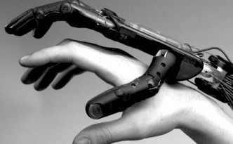 Shadow Dexterous Hand and human hand size comparison
Image: Shadow hand and human hand size comparison (Shadow Robot Company, CC BY-SA 1.0), Wikimedia Commons.

The clearest real-world example of tactile and force sensing densely integrated into a single product is the "Shadow Dexterous Hand," made by London-based Shadow Robot Company. This prosthetic-style robot hand has 24 joints with 20 degrees of freedom (exceeding a human hand), and in its electric-motor-driven version, 20 individual DC motors independently control each joint. Every joint has a built-in Hall-effect position sensor, and a force sensor is added at every degree of freedom, bringing the total to a nominal 129 sensors packed into a single hand. The fingertips can optionally be fitted with the aforementioned BioTac, which, combined with the standard pressure-pad tactile sensors, lets the hand simultaneously capture three kinds of sensory information: joint position, joint torque, and fingertip pressure distribution.
This hand has been deployed at multiple research institutions, including NASA, Bielefeld University, and Carnegie Mellon University, as well as in the EU research project "HANDLE," making it one of the de facto standards for prosthetics and teleoperation research that require both human-like degrees of freedom and a dense sensor network. Because a single maker designs, builds, and integrates all three sensor systems — joint position, force, and tactile — in-house and ships them as one product, it is a good example of how the force and tactile sensor technologies covered in this article actually get integrated into "a single hand."
Google DeepMind's three-finger compromise, and the mystery of da Vinci's missing sense of touch
Shadow Robot started as a hobby group in an attic — According to Shadow Robot Company founder Richard Greenhill, the company's origin traces back to 1987, to a group of hobbyist robot enthusiasts who met in the attic of a London home. When they posted a wooden prototype hand to an internet hobbyist bulletin board, it caught the attention of a university, opening the door to serious development. It is an unusual origin story for the robotics industry — a hobby gathering that grew into a maker of prosthetic-style robot hands now used by NASA and Carnegie Mellon University.
DEX-EE, the new hand built with Google DeepMind, chose three fingers — Shadow Robot developed a new robot hand for AI machine-learning research, "DEX-EE," jointly with Google DeepMind. Unlike the earlier Dexterous Hand, which aimed to faithfully replicate the human hand, DEX-EE deliberately opts for three sturdy fingers instead of five, and is built somewhat larger than a human hand, prioritizing the robustness needed to survive real-world trial-and-error reinforcement learning. Each finger has four joints driven by five maxon DCX16 motors through tendon drive, and carries "hundreds of channels" of tactile sensing per finger. After enduring over 1,000 hours of durability testing, it is used as a research platform for tasks like manipulating a Rubik's Cube, connecting connectors in tight spaces, and operating while absorbing repeated impacts. It is a concrete example of a shift in design philosophy — away from the industry's long pursuit of "mimicking the human hand" and toward prioritizing "a robust machine that's easy to train."
The paradox of da Vinci, a surgical robot that long went without a sense of touch — One of the applications where force and tactile sensing seems most likely to pay off is surgery, which demands extremely delicate force control. And yet the da Vinci system, made by Intuitive Surgical, the world's most widely deployed surgical robot, has been used in clinical practice for years without any function that returns direct force/haptic feedback to the surgeon. Surgeons had to judge, from visual information on a screen alone, how much force they could apply without tearing tissue, relying on experience and visual estimation. Researchers have long pursued alternatives such as visual force displays (visual feedback) and external haptic-feedback devices to compensate, but a next-generation model, da Vinci 5, incorporating what Intuitive calls "certified haptic feedback," only appeared quite recently — a striking example of how the clinical application of force sensing, which is becoming standard across robotics generally, has been remarkably slow to arrive in surgical robotics.
2025 research into low-cost sensing for grasping fragile objects — A June 2025 paper, "FORTE: Tactile Force and Slip Sensing on Compliant Fingers for Delicate Manipulation" (Shang, Seo, Zhu, Chin; arXiv:2506.18960), with participation from an MIT-founded robotics startup, proposes a low-cost sensing method that runs air channels through a 3D-printable Fin Ray-structured gripper to detect force and slip with low latency. The system achieved force-estimation accuracy within ±0.2N over a 0–8N range, slip-detection latency under 100 milliseconds, a 92% success rate grasping fragile foods such as raspberries and potato chips, and 93% slip-detection accuracy. In contrast to high-precision, high-price commercial sensors from makers like ATI and XELA, it's an example of how "cheap, DIY-able tactile sensing" continues to be pursued at the research frontier.
Parameters that determine performance
- Gauge factor and resolution: A semiconductor piezoresistive sensor has a gauge factor tens of times higher than a metal-foil sensor, letting it detect finer force changes for the same amount of strain. The ATI Axia80's 1/10N resolution is one example of the level needed for delicate assembly work, such as force control fine enough not to crack an eggshell
- Sampling rate: A high sampling rate, like the Bota SensONE's up to 2000Hz, matters for collision detection and fast force-control loops (such as impedance control). In safety functions that stop a robot arm the instant it detects contact with a person, this response speed translates directly into safety performance
- Taxel density and spatial resolution: An array-type sensor like XELA's uSkin is suited to coarsely capturing the pressure distribution across a whole fingertip or palm, whereas an optical sensor like GelSight's DIGIT specializes in a single point to reconstruct sub-millimeter-scale shape. Optical sensing has the edge for detecting object texture or fine slip; array-type sensing has the edge for grasping the overall force balance across a broad contact area
- Number of sensing modalities: A sensor like BioTac, which measures pressure, vibration, and temperature simultaneously, can also be applied to estimating material properties (such as surface smoothness or differences in thermal conductivity), but at the cost of more complex construction and a higher unit price than a single-modality sensor
- Wire count and ease of integration: A design like XELA's uSPa46, with just 7 wires relative to its taxel count, matters especially for large-area implementations that cover an entire palm. In approaches where wire count scales with taxel count, wiring becomes cumbersome and implementation cost jumps even just to cover a single finger
- Durability and cost: As with DIGIT's replacement gel (about $40), many optical sensors treat wear and damage to the gel layer as a consumable expense. Research platforms like the Shadow Dexterous Hand or DEX-EE need to validate configurations that survive real-world operation through testing on the order of 1,000 hours
Does a wrist force sensor always reveal contact locations?
Net force and moment may not uniquely determine multiple contacts. Distinguish wrench measurement from local tactile pressure measurements.
References
- Axia80-M8 F/T sensor product page (ATI Industrial Automation)
- Axia80-M20 F/T sensor product page (ATI Industrial Automation)
- ATI Axia80 F/T sensor (Universal Robots marketplace)
- SensONE 6-axis force/torque sensor product page (Bota Systems)
- Bota Systems launches upgraded force/torque sensor for small cobots (The Robot Report)
- uSkin product lineup (XELA Robotics)
- XELA Robotics integrates tactile sensors into the Tesollo DG-5F hand (Engineering.com)
- DIGIT: A Novel Design for a Low-Cost Compact High-Resolution Tactile Sensor (GelSight-related paper PDF)
- GelSight official site
- BioTac product page (SynTouch)
- Multimodal Tactile Sensor materials (USC Viterbi)
- Shadow Dexterous Hand (Wikipedia)
- Dexterous Robotic Hands Part 2: How the Shadow Dexterous Hand is Revolutionizing Robotics (Wevolver)
- The holy grail of robotics: Inside the quest to build a mechanical human hand (Digital Trends)
- Shadow Robot and Google DeepMind's new robot hand "DEX-EE" (maxon group)
- Effects of Visual Force Feedback on Robot-Assisted Surgical Task Performance (PMC)
- Role of haptic feedback technologies for surgical training and robot-assisted surgery (Frontiers in Robotics and AI)
- Invention of the Strain Gauge, Arthur Ruge, 1938 (MIT Museum)
- Edward E. Simmons (Wikipedia)
- Arthur Claude Ruge (Wikipedia)
- A Tutorial on Mechanical Sensors in the 70th Anniversary of the Piezoresistive Effect (PMC)
- FORTE paper (arXiv:2506.18960)
- Robotic Hand at Hannover Messe 2016 (Wikimedia Commons)
- Shadow hand and human hand size comparison (Wikimedia Commons)
Current step · 16 / 21 · Sensors & Hardware
Comments
Please log in to post a comment
No comments yet.