Contents — find the section you need
Background and reading guide
Background Units used in specifications, such as voltage, current, distance and time.
Fundamentals · Explanations of principles, structure and trade-offs.
A temperature sensor converts the temperature of an object or its surrounding environment into an electrical signal. But "temperature sensor" is not a single technology — it spans at least four distinct physical principles that coexist side by side: thermocouples, which use the electromotive force generated at a junction of two dissimilar metals; RTDs and thermistors, which use the way electrical resistance in metals or semiconductors changes with temperature; semiconductor IC sensors, which use the bandgap characteristics of silicon; and non-contact radiation thermometers, which detect the infrared radiation an object emits directly. From motor windings and battery cells to CPUs, exhaust gas, food, and the human body, temperature is the physical quantity that has to be monitored first in nearly every mechanical system, from autonomous mobile robots to data centers — and it works quietly behind the scenes of many other sensor technologies, from thermal-runaway detection in batteries to winding-overheat protection in actuators.
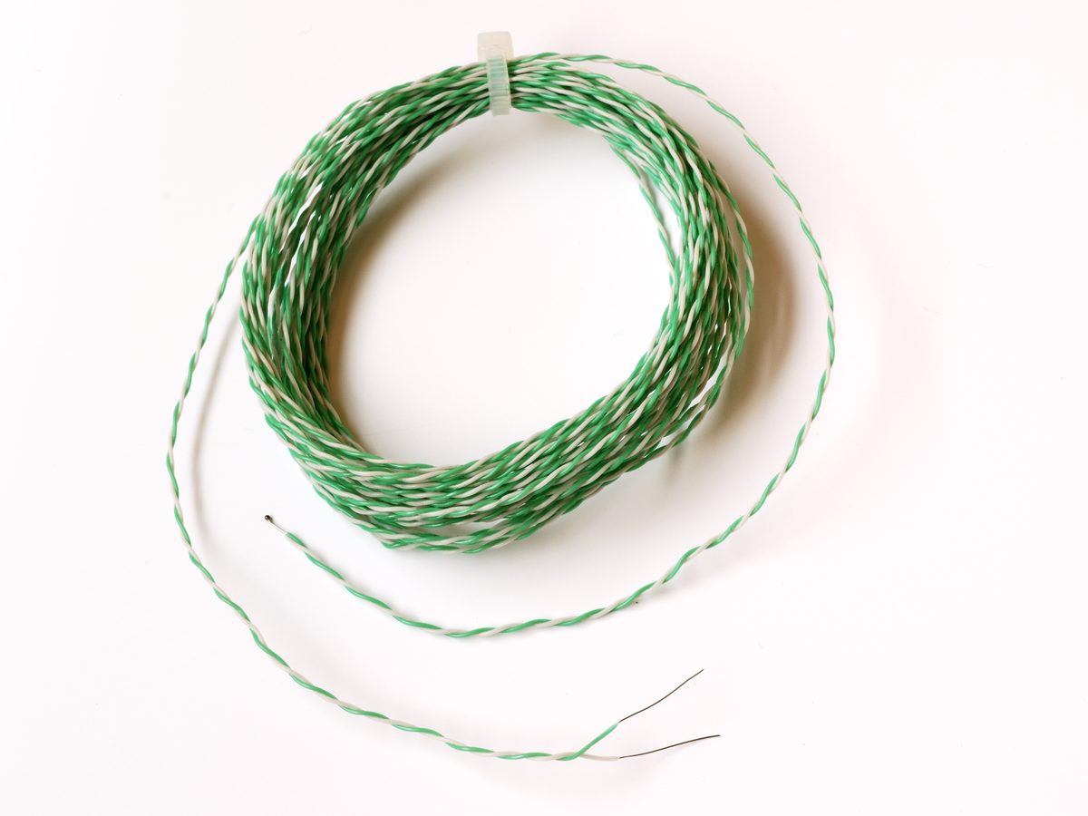 Type K thermocouple (welded junction, sheathed wire)
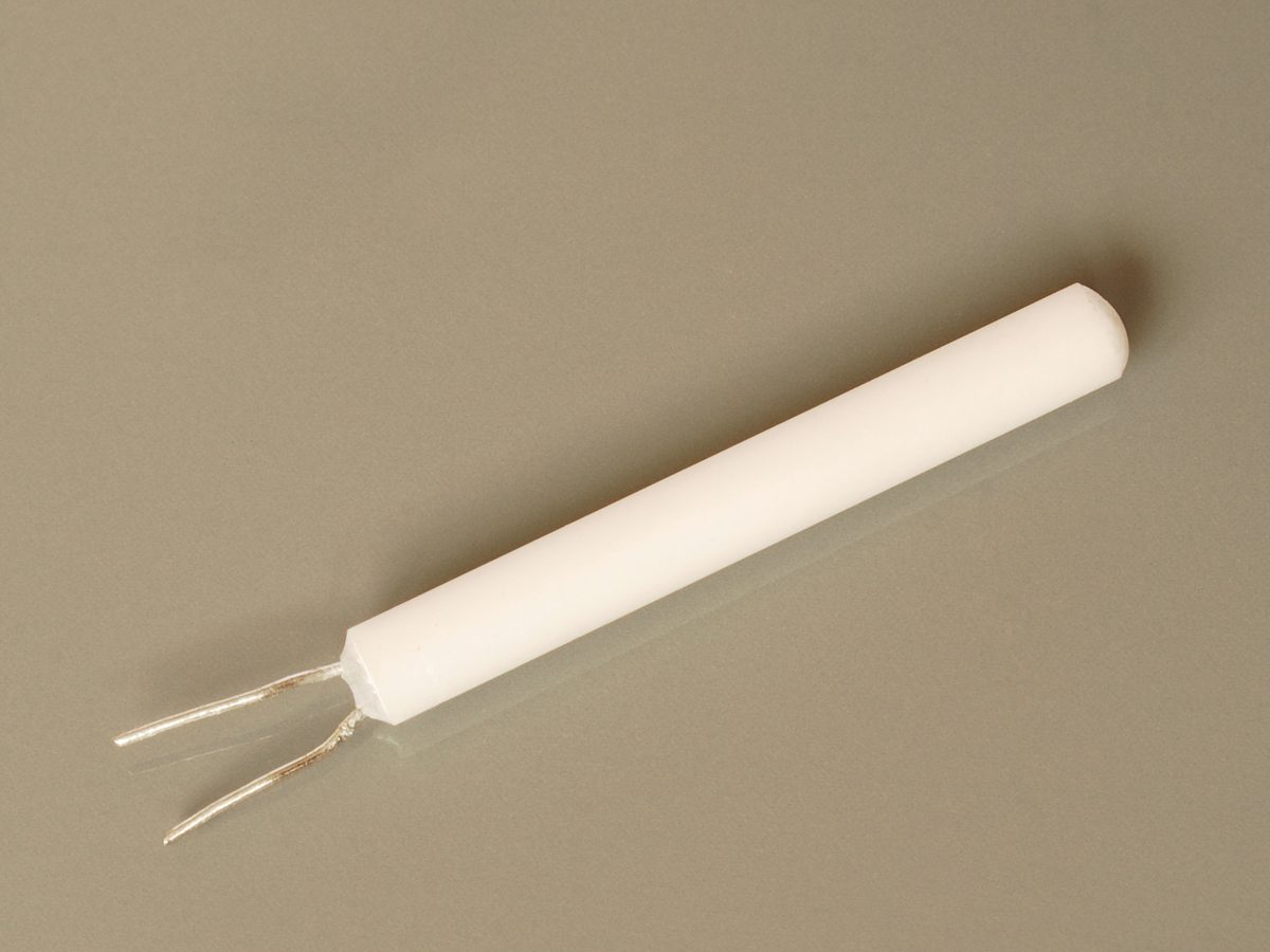 Wire-wound PT100 element (3mm diameter)
Images: Thermocouple K (3) (Harke, public domain) / Wire Wound Pt100 Resistor (Harke, CC BY-SA 3.0), Wikimedia Commons.
.jpg)

Principles: Four Different Physical Effects That "Turn Temperature Into Electricity"
Thermocouples — The Seebeck Effect and Electromotive Force Between Dissimilar Metals
A thermocouple joins one end of two different metal wires together; when a temperature difference exists between that junction (the measuring junction) and the opposite end (the reference junction), it generates an electromotive force (thermal EMF) proportional to that difference. This is the Seebeck effect, and the EMF V can be approximated using the temperature difference \Delta T = T_1 - T_0 and the Seebeck coefficient S as follows.
The most widely used Type K thermocouple (a Chromel-Alumel pairing) has a Seebeck coefficient of roughly 41\,\mu V/°C, and the convenience of staying nearly constant across a wide 0–1000°C range. However, a thermocouple can only measure "the temperature difference between two points," so determining the absolute temperature at the measuring junction requires separately knowing the reference-junction temperature. The classic method was "ice-point compensation" — immersing the reference junction in ice water (0°C) — but modern instruments typically place a separate sensor (a thermistor or semiconductor temperature sensor) near the reference junction, measure its temperature, and correct for it mathematically, a built-in technique known as Cold Junction Compensation (CJC). Thermocouples are standardized under IEC 60584 (the international standard) and ASTM E230 (the North American standard); the standard accuracy class for a Type K thermocouple is IEC 60584 Class 2, roughly \pm 2.2°C or \pm 0.75\% of reading, whichever is greater, with the higher-precision Class 1 reaching about \pm 1.5°C.
The basic thermocouple circuit: a thermal EMF arises according to the temperature difference between the measuring junction T1, where two dissimilar metal wires A and B are joined, and the reference junction T0 held at the voltmeter side (conceptual diagram created by Duskcoil).
RTDs — How a Metal's Resistance Changes With Temperature
A Resistance Temperature Detector (RTD) exploits the fact that a metal's electrical resistance rises nearly linearly as temperature increases. The most common variant is "Pt100," made from high-purity platinum, which reads 100Ω at 0°C and about 138.5Ω at 100°C. The relationship between resistance and temperature is defined by the international standard IEC 60751 as the "Callendar-Van Dusen equation," which above 0°C takes the following quadratic form.
Here R_0 is the resistance at 0°C (100Ω for a Pt100), and the coefficients are strictly fixed by the standard as A = 3.9083 \times 10^{-3}\,°C^{-1} and B = -5.775 \times 10^{-7}\,°C^{-2} (below 0°C a further cubic term C is added). RTD accuracy is expressed via the tolerance classes of IEC 60751: Class A is \pm(0.15 + 0.002|T|)°C and Class B is \pm(0.3 + 0.005|T|)°C, giving a high-precision \pm 0.15°C for Class A near 0°C, while at 100°C even Class A widens out to \pm 0.35°C — the tolerance grows in absolute terms as temperature rises. That's the opposite pattern from thermocouples, and it means RTDs are dramatically more accurate near 0°C. Because this is a resistance measurement, avoiding the influence of lead-wire resistance requires separating current excitation from voltage sensing across four wires — "4-wire" wiring is the baseline for high-precision applications.
Thermistors — A Semiconductor's Exponential Resistance Change
Thermistors belong to the same resistance-temperature family as RTDs in principle, but by using a metal-oxide semiconductor instead of a metal, they achieve a far larger rate of resistance change than an RTD. The dominant type has a negative temperature coefficient (NTC), and its resistance-temperature behavior is approximated by the following beta equation.
Here T and T_0 are absolute temperatures (K), and \beta is a material-specific constant, typically around 3000–4000K for common products. Because the response is exponential, where an RTD's resistance changes by under 40% over a 100°C swing, a thermistor's resistance changes by orders of magnitude more over the same swing, making it well suited to high-sensitivity detection over a narrow temperature range. The tradeoff is that this nonlinear sensitivity makes it hard to cover a wide temperature range with a single equation — in practice, engineers use lookup tables at multiple temperature points, or a higher-order approximation such as the Steinhart-Hart equation. A rarer variant with a positive temperature coefficient (PTC) also exists; rather than a smooth response, its resistance jumps sharply once a threshold temperature is crossed, a property exploited for inrush-current limiting in power circuits and self-resetting fuses — the NTC photo above is itself an example of an inrush-current-limiting device on a power supply board.
Semiconductor IC Sensors — The Bandgap and PN-Junction Temperature Dependence
The forward voltage across a silicon PN junction (such as the base-emitter junction of a diode or transistor), held at a constant current, drops nearly linearly as temperature rises (roughly -2mV/°C for silicon). This dependence alone doesn't reproduce reliably against absolute temperature, but by combining two current components with different temperature dependences to build a temperature-independent reference voltage (a bandgap reference), and extracting only the temperature component from the residual, engineers get a "PTAT" (Proportional To Absolute Temperature) circuit — the core technology inside modern semiconductor temperature sensor ICs. Texas Instruments' (formerly National Semiconductor's) LM35, launched in the 1980s, was a pioneering product that turned this principle into an analog voltage output (10mV/°C), delivering \pm 1/4°C accuracy near room temperature and \pm 3/4°C across its full -55 to 150°C range without external calibration, all in a simple output format. Later, products that digitize this temperature signal with an on-chip ADC and read it out directly over a digital bus such as I2C or 1-Wire became mainstream, evolving into 1-Wire ICs like Maxim's (now Analog Devices') DS18B20 and \pm 0.1°C-class high-precision I2C sensors like the TMP117.
Non-Contact (Infrared Radiation Thermometers) — The Stefan-Boltzmann Law, and an Unexpected Reappearance of the Thermocouple
Infrared radiation thermometers measure temperature without contact by exploiting the physical law that an object radiates infrared energy in proportion to its absolute temperature (the Stefan-Boltzmann law). Radiant energy per unit area P can be expressed using the emissivity \varepsilon (a coefficient from 0 to 1 describing how close a surface is to an ideal blackbody) and the Stefan-Boltzmann constant \sigma as follows.
Because this scales with the fourth power of temperature, even a small temperature change produces a large change in radiant energy, which a sensor can capture to determine temperature without contact. What's interesting here is that many of the detector elements that actually convert this infrared energy into an electrical signal are called "thermopiles" — structures built from countless microscopic thermocouples connected in series. When infrared from a target object is absorbed by the detector's receiving surface, that surface warms slightly, and the array of thermocouples reads that temperature rise, cumulatively, as a difference against a reference surface on the back side — the Seebeck effect, discovered in the 19th century, is still hard at work underpinning one of the most modern forms of temperature sensing: non-contact, remote detection. Melexis' MLX90614 is a representative example of a digital-output IC that integrates this thermopile approach into a single chip. Two-dimensional thermal-imaging cameras (such as the FLIR Lepton), on the other hand, mostly use a different approach called a "microbolometer" rather than a thermopile. This is a device that reads the pixel-by-pixel temperature rise from absorbed infrared using the same "resistance's temperature dependence" principle as RTDs and thermistors — meaning both of the resistance-based and thermocouple-based principles covered in this article are, in different forms, alive and well inside non-contact infrared sensing, an interesting coincidence in the lineage of temperature-sensing technology.
Spec Comparison of Major Products
| Product | Maker | Detection method | Temperature range | Accuracy | Notes |
|---|---|---|---|---|---|
| KTSS series (Type K thermocouple probes) | Omega Engineering (US) | Thermocouple | -200 to 900°C with stainless sheath (up to ~1150°C with Inconel 600 sheath) | Standard class: ±2.2°C or ±0.75%, whichever is greater | General-purpose miniature connector support; a go-to probe for high-temperature measurement in industrial furnaces and exhaust systems |
| M222 (Pt100 thin-film element) | Heraeus Nexensos (Germany) | RTD | -70 to +500°C | Selectable from Class A (±0.15°C @0°C) to Class C (±0.6°C @0°C) | 2.3×2.1×0.9mm thin-film element, compliant with DIN EN IEC 60751, widely used across automotive, industrial measurement, and medical devices |
| NTCLE100E3 | Vishay (US) | NTC thermistor | -40 to +125°C | Resistance tolerance ±5%, beta tolerance ±0.75% | 10kΩ at 25°C, β=3977K, radial-lead package used generally from power-supply inrush-current limiting to sensing |
| DS18B20 | Analog Devices (formerly Maxim) | Semiconductor IC (1-Wire digital output) | -55 to +125°C | ±0.5°C over -10 to 85°C | Multiple units can be daisy-chained on a single signal wire via the 1-Wire bus; selectable 9–12 bit resolution (0.5–0.0625°C steps) |
| TMP117 | Texas Instruments (US) | Semiconductor IC (I2C digital output) | -55 to +150°C | ±0.1°C over -20 to 50°C, ±0.25°C even over -55 to 125°C | 16-bit resolution at 0.0078°C, low 3.5µA supply current, delivers PT100-class accuracy on a single chip |
| MLX90614 | Melexis (Belgium) | Non-contact infrared (thermopile) | Object -70 to +382.2°C, ambient -40 to +125°C | Standard ±0.5°C (medical-grade ±0.1°C option available over a limited range) | SMBus digital output, 0.02°C resolution, integrates a 17-bit ADC and signal-processing ASIC into a single TO-39 can |
Omega's KTSS series is a standard thermocouple probe line for high-temperature, harsh environments like industrial furnaces and exhaust gas, and it supports a miniature connector standard that plugs directly into handheld instruments. Heraeus' M222 is a representative thin-film Pt100 element built into mass-produced equipment, from automotive engine control and anti-lock brakes to home appliance temperature management, and it's notable for offering the standard's Class A through C tolerances directly as product-line options. NTC thermistors like Vishay's NTCLE100E3 sit in the tens-of-cents-to-a-dollar price range, and are used at orders-of-magnitude higher production volumes than the pricier alternatives, in exchange for lower cost, from power-supply inrush-current limiting to cell-temperature monitoring in lithium-ion battery packs.
The DS18B20's biggest feature is the 1-Wire bus itself — a communication method that lets multiple sensors be daisy-chained on a single signal wire — and it has long held de facto standard status in the hobbyist electronics community around Arduino and Raspberry Pi. TMP117 is another semiconductor IC, but aimed at a step up in accuracy from the DS18B20; as Texas Instruments itself positions it, it "can serve as a substitute for PT100 in non-medical applications," packing RTD-class accuracy into a single chip. The MLX90614 is a representative non-contact sensor chosen for applications where you want to measure without touching the target — the surface temperature of a rotating object, or food and medical fields where contamination must be avoided.
History: From a Discovery Mistaken for Electricity, to Managing Heat in a Laptop
Seebeck Misread His Own Discovery as "Magnetism"
The Seebeck effect, the principle underlying thermocouples, was discovered in 1821 by the German physicist Thomas Johann Seebeck. Seebeck was running an experiment in which he joined two different metals (copper and bismuth) into a loop and applied a temperature difference across the junction, and he noticed that a nearby compass needle deflected. From this, Seebeck concluded that "the temperature difference magnetized the metal, and that magnetism deflected the compass," and he tried to explain the phenomenon by tying it to Earth's magnetism and volcanic activity. In reality, the temperature difference drove a current through the circuit, and it was the magnetic field created by that current that deflected the compass — in other words, Seebeck had discovered electricity, but published his findings while still misunderstanding it as a magnetic phenomenon. Hans Christian Ørsted later correctly reinterpreted the phenomenon as an electrical one, and today, combined with the Peltier effect, it's known as the "Peltier-Seebeck effect." That the discoverer himself misidentified the true nature of his own discovery is an unusual episode still cited repeatedly in the history of science.
Callendar Rescued the Platinum Resistance Thermometer From Being "Useless"
The origin of the RTD traces to 1871, when the German-born engineer William Siemens presented a temperature-measurement method based on the temperature dependence of electrical resistance in a Bakerian Lecture. However, a committee at the British Association for the Advancement of Science, including Lord Kelvin and James Clerk Maxwell, examined the device at the time and issued a critical report, pointing out a flaw in which insulating material placed stress on the platinum and destabilized its resistance value. It was the British physicist Hugh Longbourne Callendar who broke through this impasse; around 1885 he improved the insulating material and secured stability by annealing at temperatures beyond the intended measurement range's upper limit. The resistance-temperature approximation Callendar formulated achieved accuracy within 1% over a 600°C range, and this became the prototype for today's Callendar-Van Dusen equation. The roughly 30 years it took — from Siemens' original proposal, through Callendar's improvements, to the RTD's establishment as a real measuring instrument — illustrates that discovering a sound principle and the engineering perseverance needed to actually make it usable are two very different things.
The Thermistor Principle Faraday Spotted 150 Years Ago
The phenomenon underlying thermistors — that a semiconductor's resistance drops as temperature rises — was first recorded by Michael Faraday, known as the discoverer of electromagnetic induction. In 1833, Faraday observed that the electrical resistance of silver sulfide decreased dramatically as temperature rose, and this is considered the first scientific record ever to demonstrate a semiconductor property. However, it took roughly 100 years for this phenomenon to reach the market as an actual product; commercial production finally began in 1930, when the American inventor Samuel Ruben established a practical manufacturing process. Ruben later also contributed to the practical development of mercury and alkaline batteries, and is also known as a battery researcher. The fact that it took nearly a century from the discovery of the underlying phenomenon to practical use stands in contrast to the Seebeck effect, discovered in the same 19th century, which was put into practical use as the thermocouple relatively quickly.
The Man Known as the "Czar of Bandgaps"
The engineer whose mastery of the bandgap-reference circuit design at the heart of semiconductor temperature-sensor ICs is still spoken of across the industry is Robert (Bob) Pease of National Semiconductor (now under Texas Instruments). Pease joined the company in 1976, and over his 33-year tenure worked on 21 patents and more than 20 integrated circuit designs, earning the nickname "Czar of Bandgaps" from colleagues for his exceptional analog design skill. He is also known for his deep involvement in developing and evaluating temperature sensor ICs, including the LM35, and there's an anecdote that he calibrated the LM35 using an ultra-high-precision, ultra-stable temperature-controlled bath he built himself for the purpose. The technique of squeezing millikelvin-class temperature resolution out of a silicon chip alone, while absorbing semiconductor process variation and manufacturing error, is an extension of the craftsmanship built up by a small handful of analog designers like Pease.
A Real-World Case: An F1 Car Measures Its Tires "Without Touching Them," Using 12 Non-Contact Sensors
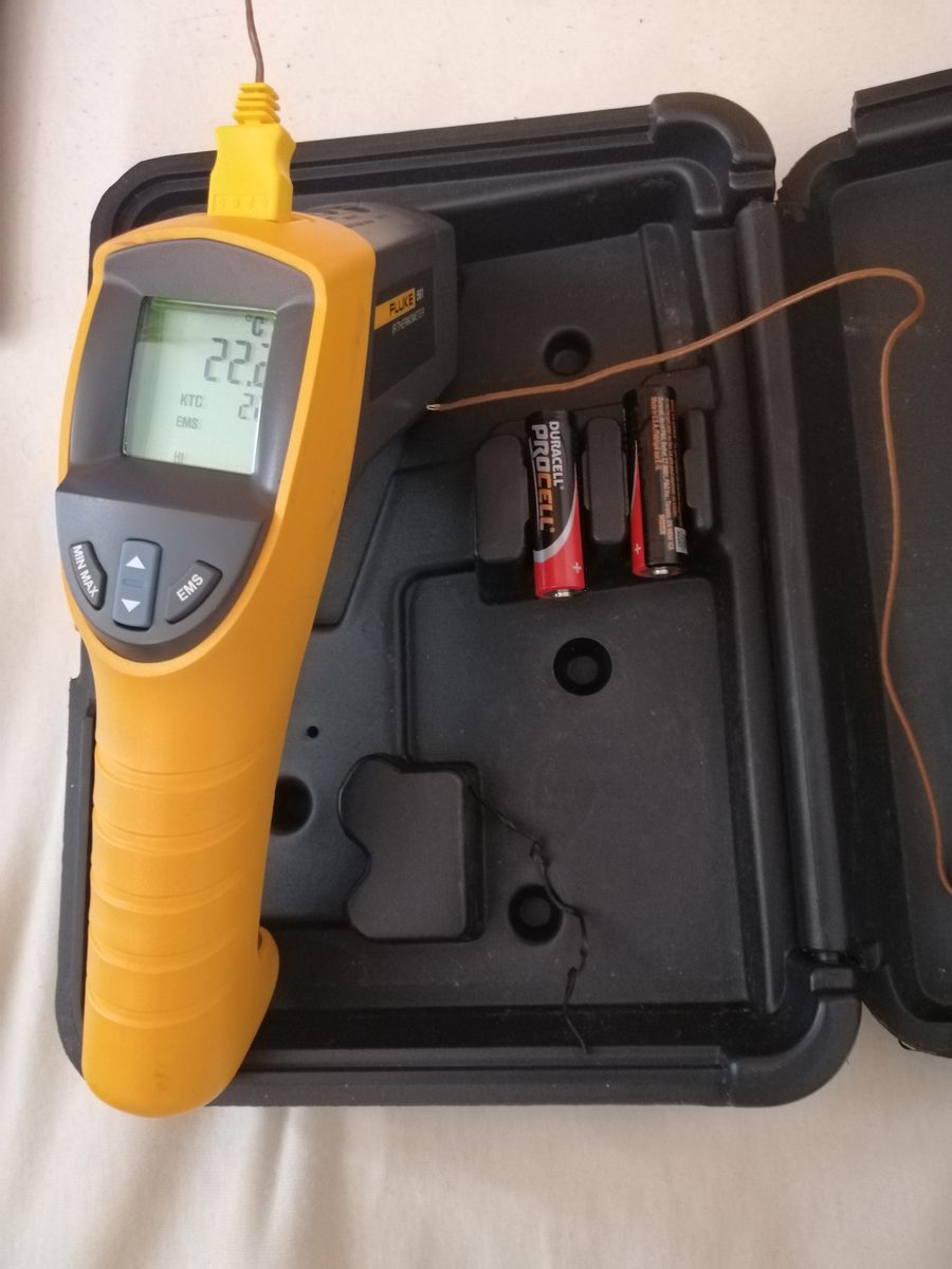 Fluke 561 infrared thermometer (with a Type K thermocouple probe)
Image: Industrial infrared thermometer with additional temperature probe (KalWadin, CC BY-SA 4.0), Wikimedia Commons. An example of a handheld device that combines both non-contact infrared detection and a contact-type thermocouple probe in one unit.

One real-world case that shows temperature sensors truly earning their keep — under both multi-unit and non-contact conditions — is tire-temperature monitoring on Formula 1 (F1) cars. F1 tire grip characteristics change dramatically with rubber temperature, so measuring surface temperature in real time and without contact while the car is running feeds directly into both setup tuning and race strategy. The product used here is the "IRN8C-F1" infrared array sensor developed by France's Texense, said to be used by more than 90% of teams on the 2020s F1 grid. The device packs eight channels of infrared detector elements into a single housing, letting it read the temperature distribution at 8 points across a tire's width in one shot, and it's optimized to measure from a distance of up to 950mm. On an actual car, the typical configuration places a sensor at each of the four wheels; when multiple units are used per tire (three, for inside/outside/center-point measurement, for example), a car can carry up to roughly 12 IR sensors monitoring the tire surfaces in real time. Attaching contact-type thermocouples or RTDs directly to a tire surface that's spinning and moving at high speed is close to physically impossible — the very principle of non-contact detection based on the Stefan-Boltzmann law is the precondition that makes this application possible at all.
The "Invisible Temperature Drift" Quietly Eating Into Force-Sensor Accuracy
Temperature sensors aren't only used on their own — they also quietly support, or quietly corrupt, the accuracy of other sensors. A paper published in February 2025, "Temperature Compensation Method of Six-Axis Force/Torque Sensor Using Gated Recurrent Unit" (Hyun-Bin Kim, Seokju Lee, Byeong-Il Ham, Kyung-Soo Kim), examines how badly the accuracy of a six-axis force/torque (F/T) sensor is eaten into by temperature change. A photocoupler-based F/T sensor's lightweight 45g design gives it a small thermal mass, so even a small amount of heat generation causes the internal temperature to swing sharply, driving changes in dark current that degrade real-time force and torque estimation accuracy. Rather than the conventional multilayer perceptron (MLP) or least-squares-based temperature correction, this paper proposes a correction method using a GRU (Gated Recurrent Unit), which handles time-series data, and reports accuracy improvements over the conventional methods. It's an easy thing to overlook when reading a force sensor's catalog spec sheet, but drift from the sensor's own heat generation and ambient temperature fluctuation is a hidden factor that throws off a robot arm's precise force control in real-world operation, and research combining temperature sensing with machine learning to correct for it is still ongoing today.
Parameters That Determine Performance
- Measurement principle vs. temperature range: A Type K thermocouple can cover an extremely wide -200 to 1350°C range, while an RTD (Pt100) covers -200 to 850°C, thermistors around -55 to 150°C, and semiconductor ICs -55 to 125°C for the DS18B20 or -55 to 150°C for the TMP117 — the higher the temperature, the more the choices narrow down to thermocouples. Semiconductor ICs and thermistors simply can't be used in high-temperature environments like exhaust gas or industrial furnaces
- Accuracy vs. temperature dependence: An RTD (Class A, ±0.15°C near 0°C) or a TMP117 (±0.1°C over -20 to 50°C) delivers high accuracy over a narrow temperature band, but the tolerance itself widens as temperature rises. A thermocouple's standard accuracy (±2.2°C or ±0.75%), by contrast, holds roughly as a constant proportional error across the entire temperature range, making it suited to applications that prioritize robustness across a wide, high-temperature range over absolute accuracy
- Response speed and thermal mass: Thermistors and thermocouples have small elements with low thermal mass, so they respond quickly, while an encapsulated RTD element has higher thermal mass and tends to respond more slowly. A non-contact type like the MLX90614 doesn't need to touch the target or wait for thermal equilibrium, so it can track temperature instantly even on targets where contact measurement is difficult, such as a rotating surface
- Self-heating: Thermistors and RTDs both require a current to be passed through them for measurement, and that current itself generates Joule heat that slightly warms the element. The fact that the LM35 keeps self-heating under 0.1°C at just 60µA of supply current, and that the TMP117 touts a low 3.5µA draw, shows that suppressing self-heating becomes a central design focus the further accuracy is pushed
- Wiring and implementation cost: Chasing high accuracy with an RTD requires 4-wire wiring, which increases wiring cost, whereas the DS18B20's 1-Wire bus can daisy-chain multiple units on a single signal wire, dramatically reducing wire count for multi-point measurement. In applications like EV battery packs that need dozens to hundreds of temperature monitoring points, this difference in wire count translates directly into implementation cost
- The value of the non-contact option: As the IRN8C-F1 in F1 shows, when a target spins at high speed, contamination must be avoided, or contact itself would disturb what's being measured, non-contact measurement based on the Stefan-Boltzmann law determines whether measurement is even possible in the first place, before accuracy even enters the picture. That said, getting the emissivity \varepsilon setting wrong throws the reading off significantly, so understanding a target's surface characteristics (gloss, material) matters even more than with contact-type sensing
Is thermal-camera temperature independent of material?
Emissivity, reflections, transmission, and viewing conditions affect apparent temperature. Color differences alone do not establish precise temperature differences.
References
- LM35 Precision Centigrade Temperature Sensors datasheet (Texas Instruments, official PDF)
- TMP117 High-Accuracy, Low-Power, Digital Temperature Sensor product page (Texas Instruments, official)
- DS18B20 Programmable Resolution 1-Wire Digital Thermometer datasheet (Analog Devices, official PDF)
- MLX90614 datasheet (Melexis, official PDF)
- Heraeus Nexensos M222 datasheet (Mouser-distributed PDF)
- Vishay NTCLE100E3 datasheet (Vishay, official PDF)
- Omega Engineering KTSS series thermocouple probes product page
- K-Type Thermocouples explainer (DwyerOmega official blog)
- Thermocouple Accuracy, Tolerances and Error Sources (TE Instrumentation)
- RTD Accuracy Classes - Class AA, A, B, Pt100 and Pt1000 (Thermometrics)
- Callendar–Van Dusen equation (Wikipedia)
- The Origin of the Platinum Resistance Thermometer (Johnson Matthey Technology Review)
- Hugh Longbourne Callendar (Wikipedia)
- Thermistor (Wikipedia, background on Faraday 1833 and Ruben 1930)
- Thomas Johann Seebeck (Wikipedia, on the discovery and the misunderstanding)
- Bob Pease (Wikipedia, background on the "Czar of Bandgaps")
- Bob Pease—the "Czar of Bandgaps" and His Analog Design Legacy (All About Circuits)
- FLIR Lepton series datasheet (Teledyne FLIR, official PDF)
- Texense IRN8C-F1 infrared tire temperature sensor product page (Fama Engineering)
- Formula 1's testing sensors explained (RACER)
- Temperature Compensation Method of Six-Axis Force/Torque Sensor Using Gated Recurrent Unit (arXiv:2502.17528)
Current step · 15 / 21 · Sensors & Hardware
Comments
Please log in to post a comment
No comments yet.