Contents — find the section you need
A drive cannot directly set mechanical speed. It creates voltage, changes winding current and magnetic field, then produces torque that changes rotation. Field-oriented control (FOC) uses coordinates aligned with the rotating field to simplify current control. This introduction focuses on a permanent-magnet synchronous motor (PMSM).
Separate current, torque and speed
A simplified mechanical equation is:
J is inertia [kg m²], ω mechanical angular velocity [rad/s], Te electromagnetic torque [N m], TL load torque [N m] and B viscous resistance [N m s/rad]. Greater torque need not change speed immediately under substantial inertia or load. Maintaining constant speed can also require torque.
Outer speed loop, inner current loop
Speed error drives a PI controller producing a torque-related current reference. Inner current PI controllers generate voltage references; PWM realizes them through inverter switching.
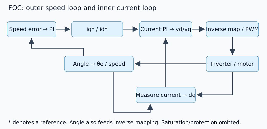
An asterisk denotes a reference. Outer-loop design assumes sufficiently responsive current tracking, but no universal bandwidth ratio can ignore plant dynamics and delay. Sections 4–5 of the TI PMSM FOC report explain transformations and the basic structure. This is an original explanatory schematic, not a product circuit diagram.
View three phases in rotating coordinates
Clarke transformation maps phase currents to stationary αβ axes; Park transformation rotates them into rotor-flux-aligned dq axes. d follows flux and q is perpendicular. This assumes negligible zero sequence in balanced phases and consistent amplitude/power normalization.
For a simplified surface-magnet motor at lower speeds, an appropriately defined torque constant permits Te≈Kt iq. A hypothetical Kt=0.10 N m/A and iq=3 A give 0.30 N m. This is arithmetic under an explicit convention, not permission to substitute phase RMS current indiscriminately. Match manufacturer constants to the dq transformation definition.
Electrical angle differs from mechanical angle
With p pole pairs, electrical angle is:
Four pole pairs turn 90° mechanical motion into 360° electrical motion. Reversed encoder direction, incorrect zero offset or confusing poles with pole pairs rotates measured currents into the wrong axes. Check angle, phase order and current-sensor signs/offsets before tuning.
id=0 is not every operating condition
A basic example often sets the d-axis reference to zero. Interior-magnet saliency, maximum-torque-per-ampere operation and high-speed field weakening require other references. Increasing back EMF can also prevent current tracking within the available DC-bus voltage.
Current and voltage limits are distinct. Integrating through saturation delays recovery, motivating anti-windup. Failure to reach speed is not automatically insufficient speed gain.
Checks before implementation
This is a control-structure explanation, not a powered inverter test. Implementation must consider current-sampling timing, PWM synchronization, angle delay and protection/stop conditions. Before energizing hardware, feed known vectors and angles through dq and inverse transformations and verify round trips.
Use the PID experiment to examine saturation and integration, then the reducer introduction to connect motor/load speed, torque and inertia.
Comments
Please log in to post a comment
No comments yet.