Contents — find the section you need
Change parameters and verify
Open the panel, then press Run to load Python. You can stop execution and reset parameters. Results are computed on this device. No Python installation is required.
Local execution steps below are optional for reproducing the source results; they are not required for the browser experiment.
The experiment controls are in English.
Explore current coordinates and electrical angle
The panel above is a one-instant coordinate exercise. Supply actual current components in the true rotor frame, mechanical angle, pole-pair count, an electrical-angle error, and a hypothetical torque constant. It constructs balanced phase currents and transforms them back using the supplied estimated angle. These are imposed currents, not current references tracked by a controller. No motor, inverter or local Python is required.
The convention is explicit: α aligns with phase a; β is +90° counterclockwise from α. The true d axis follows rotor flux at θe=p θm, with fixed zero offset 0; q leads d by +90°. Positive angles are counterclockwise. p counts pole pairs, not poles. The display includes unwrapped electrical angle and its modulo-360° direction. Four pole pairs and 90° mechanical angle give 360° electrical angle, equivalent to 0° for the transforms. Changing p here changes the angle mapping only; the separately supplied torque constant stays fixed.
We use amplitude-invariant Clarke normalization with zero sequence fixed to zero. With R(θ)=[[cosθ,−sinθ],[sinθ,cosθ]], first form [iα,iβ]=R(θe)[id,iq]. Generate ia=iα, ib=−iα/2+√3 iβ/2, ic=−iα/2−√3 iβ/2. Thus ia+ib+ic=0. Clarke recovers iα=(2/3)(ia−ib/2−ic/2) and iβ=(ib−ic)/√3. These are instantaneous signed amperes, not phase RMS values. This amplitude normalization is not power invariant: ia²+ib²+ic²=(3/2)(id²+iq²).
The estimated angle is θ̂e=θe+Δθe. Park computes [id̂,iq̂]=R(θ̂e)ᵀ[iα,iβ]. Consequently id̂=id cosΔ+iq sinΔ and iq̂=−id sinΔ+iq cosΔ. At true id=0, iq=3 A and error +90°, the displayed estimated components become id̂=3 A, iq̂≈0. The original phase currents stay the same when only this angle error changes. The diagram shows the same stationary current vector with true and estimated axes; axis-arrow lengths are illustrative and do not encode current. All current scales are shared across A/B.
The inverse uses the same estimated angle: [iα′,iβ′]=R(θ̂e)[id̂,iq̂], then the same inverse Clarke equations. The maximum absolute reconstructed-phase difference should be small even at an incorrect angle. This residual measures algebraic consistency and floating-point roundoff; it cannot establish encoder alignment, sensor accuracy or a working FOC loop. Presets compare +/−90° errors, 180° error, mixed d/q current, zero current, negative q current, and electrical-angle wrapping. A zero vector hides every angle error.
A separate simplified nonsalient PMSM relation gives Te=Kt × true iq. Default Kt=0.10 N m/A and iq=3 A give 0.30 N m. Kt is defined for this amplitude-invariant peak-dq convention and includes the motor-specific conversion; it is not a phase-RMS constant to substitute blindly. The model omits reluctance torque and assumes constant flux. Angle error changes the displayed components but does not change imposed current or modeled torque. A real feedback loop using the wrong angle may change currents; that behavior is not simulated. Nonzero d current is a coordinate example, not a field-weakening or current-limit recommendation.
No PI control, PWM, DC-bus limits, voltage equations, speed dynamics, saliency, field weakening, sensor noise, heating, protection or hardware operation is modeled. Inputs are synthetic teaching assumptions. Use the separate PID Lab for controller behavior and the reducer Lab for mechanical transmission arithmetic.
Reference reviewed 2026-09-20: TI PMSM FOC report, sections 4–5. This exercise states its normalization and sign convention directly; it does not reproduce the report's motor-control implementation.
Bir sürücü doğrudan mekanik hızı ayarlayamaz. Gerilim oluşturur, sargı akımını ve manyetik alanı değiştirir, ardından dönüşü değiştiren tork üretir. Alan yönelimli kontrol (FOC), akım kontrolünü basitleştirmek için dönen alanla hizalanmış koordinatları kullanır. Bu giriş, kalıcı mıknatıslı senkron motor (PMSM) üzerine odaklanmaktadır.
Akım, tork ve hızın ayrılması
Basitleştirilmiş bir mekanik denklem şöyledir:
J atalet [kg m²], ω mekanik açısal hız [rad/s], Te elektromanyetik tork [N m], TL yük torku [N m] ve B viskoz direnç [N m s/rad]. Daha büyük tork, önemli atalet veya yük altında hızı hemen değiştirmek zorunda değildir. Sabit hızı korumak da tork gerektirebilir.
Dış hız döngüsü, iç akım döngüsü
Hız hatası, torkla ilgili bir akım referansı üreten bir PI kontrolörünü çalıştırır. İç akım PI kontrolörleri gerilim referansları üretir; PWM bunları invertör anahtarlaması yoluyla gerçekleştirir.
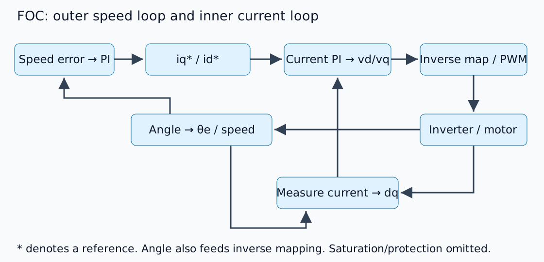
Yıldız işareti bir referansı belirtir. Dış döngü tasarımı, yeterince duyarlı akım izlemeyi varsayar, ancak hiçbir evrensel bant genişliği oranı tesis dinamiklerini ve gecikmeyi göz ardı edemez. TI PMSM FOC raporunun 4-5. bölümleri dönüşümleri ve temel yapıyı açıklar. Bu, orijinal bir açıklayıcı şemadır, ürün devre şeması değildir.
Dönen koordinatlarda üç fazı görüntüleme
Clarke dönüşümü, faz akımlarını sabit αβ eksenlerine eşler; Park dönüşümü bunları rotor akısı hizalı dq eksenlerine döndürür. d akıyı takip eder ve q diktir. Bu, dengeli fazlarda ihmal edilebilir sıfır dizisi ve tutarlı genlik/güç normalizasyonunu varsayar.
Düşük hızlarda çalışan basitleştirilmiş bir yüzey mıknatıslı motor için, uygun şekilde tanımlanmış bir tork sabiti Te≈Kt iq'ye izin verir. Varsayımsal bir Kt=0,10 N m/A ve iq=3 A, 0,30 N m verir. Bu, açık bir kurala göre yapılan aritmetik bir işlemdir, faz RMS akımını ayrım gözetmeksizin değiştirme izni değildir. Üretici sabitlerini dq dönüşüm tanımıyla eşleştirin.
Elektriksel açı, mekanik açıdan farklıdır
p kutup çifti ile elektriksel açı şöyledir:
Dört kutup çifti, 90° mekanik hareketi 360° elektriksel harekete dönüştürür. Ters çevrilmiş enkoder yönü, yanlış sıfır ofseti veya kutupların kutup çiftleriyle karıştırılması, ölçülen akımları yanlış eksenlere döndürür. Ayarlamadan önce açıyı, faz sırasını ve akım sensörü işaretlerini/ofsetlerini kontrol edin.
id=0 her çalışma koşulu değildir
Temel bir örnek genellikle d ekseni referansını sıfıra ayarlar. İç mıknatıs çıkıntısı, maksimum tork/amper çalışma ve yüksek hızlı alan zayıflaması diğer referansları gerektirir. Geri EMK'nın artması, mevcut DC bara voltajı içinde akım takibini de engelleyebilir.
Akım ve voltaj limitleri farklıdır. Doygunluktan entegrasyon, toparlanmayı geciktirir ve anti-windup'ı motive eder. Hıza ulaşamama, otomatik olarak yetersiz hız kazancı anlamına gelmez.
Uygulamadan Önce Kontroller
Bu bir kontrol yapısı açıklamasıdır, güçlendirilmiş bir invertör testi değildir. Uygulama, akım örnekleme zamanlamasını, PWM senkronizasyonunu, açı gecikmesini ve koruma/durdurma koşullarını dikkate almalıdır. Donanımı çalıştırmadan önce, bilinen vektörleri ve açıları dq ve ters dönüşümlerden geçirin ve gidiş-dönüşleri doğrulayın.
Doygunluğu ve entegrasyonu incelemek için PID deneyini, ardından motor/yük hızı, tork ve ataleti bağlamak için redüktör tanıtımını kullanın.
Yorumlar
Lütfen önce giriş yapın.
Henüz veri yok.