Contents — find the section you need
Change parameters and verify
Open the panel, then press Run to load Python. You can stop execution and reset parameters. Results are computed on this device. No Python installation is required.
Local execution steps below are optional for reproducing the source results; they are not required for the browser experiment.
The experiment controls are in English.
Explore current coordinates and electrical angle
The panel above is a one-instant coordinate exercise. Supply actual current components in the true rotor frame, mechanical angle, pole-pair count, an electrical-angle error, and a hypothetical torque constant. It constructs balanced phase currents and transforms them back using the supplied estimated angle. These are imposed currents, not current references tracked by a controller. No motor, inverter or local Python is required.
The convention is explicit: α aligns with phase a; β is +90° counterclockwise from α. The true d axis follows rotor flux at θe=p θm, with fixed zero offset 0; q leads d by +90°. Positive angles are counterclockwise. p counts pole pairs, not poles. The display includes unwrapped electrical angle and its modulo-360° direction. Four pole pairs and 90° mechanical angle give 360° electrical angle, equivalent to 0° for the transforms. Changing p here changes the angle mapping only; the separately supplied torque constant stays fixed.
We use amplitude-invariant Clarke normalization with zero sequence fixed to zero. With R(θ)=[[cosθ,−sinθ],[sinθ,cosθ]], first form [iα,iβ]=R(θe)[id,iq]. Generate ia=iα, ib=−iα/2+√3 iβ/2, ic=−iα/2−√3 iβ/2. Thus ia+ib+ic=0. Clarke recovers iα=(2/3)(ia−ib/2−ic/2) and iβ=(ib−ic)/√3. These are instantaneous signed amperes, not phase RMS values. This amplitude normalization is not power invariant: ia²+ib²+ic²=(3/2)(id²+iq²).
The estimated angle is θ̂e=θe+Δθe. Park computes [id̂,iq̂]=R(θ̂e)ᵀ[iα,iβ]. Consequently id̂=id cosΔ+iq sinΔ and iq̂=−id sinΔ+iq cosΔ. At true id=0, iq=3 A and error +90°, the displayed estimated components become id̂=3 A, iq̂≈0. The original phase currents stay the same when only this angle error changes. The diagram shows the same stationary current vector with true and estimated axes; axis-arrow lengths are illustrative and do not encode current. All current scales are shared across A/B.
The inverse uses the same estimated angle: [iα′,iβ′]=R(θ̂e)[id̂,iq̂], then the same inverse Clarke equations. The maximum absolute reconstructed-phase difference should be small even at an incorrect angle. This residual measures algebraic consistency and floating-point roundoff; it cannot establish encoder alignment, sensor accuracy or a working FOC loop. Presets compare +/−90° errors, 180° error, mixed d/q current, zero current, negative q current, and electrical-angle wrapping. A zero vector hides every angle error.
A separate simplified nonsalient PMSM relation gives Te=Kt × true iq. Default Kt=0.10 N m/A and iq=3 A give 0.30 N m. Kt is defined for this amplitude-invariant peak-dq convention and includes the motor-specific conversion; it is not a phase-RMS constant to substitute blindly. The model omits reluctance torque and assumes constant flux. Angle error changes the displayed components but does not change imposed current or modeled torque. A real feedback loop using the wrong angle may change currents; that behavior is not simulated. Nonzero d current is a coordinate example, not a field-weakening or current-limit recommendation.
No PI control, PWM, DC-bus limits, voltage equations, speed dynamics, saliency, field weakening, sensor noise, heating, protection or hardware operation is modeled. Inputs are synthetic teaching assumptions. Use the separate PID Lab for controller behavior and the reducer Lab for mechanical transmission arithmetic.
Reference reviewed 2026-09-20: TI PMSM FOC report, sections 4–5. This exercise states its normalization and sign convention directly; it does not reproduce the report's motor-control implementation.
Penggerak tidak dapat secara langsung mengatur kecepatan mekanis. Penggerak menciptakan tegangan, mengubah arus belitan dan medan magnet, kemudian menghasilkan torsi yang mengubah rotasi. Kontrol berorientasi medan (FOC) menggunakan koordinat yang sejajar dengan medan putar untuk menyederhanakan kontrol arus. Pendahuluan ini berfokus pada motor sinkron magnet permanen (PMSM).
Memisahkan arus, torsi, dan kecepatan
Persamaan mekanis yang disederhanakan adalah:
J adalah inersia [kg m²], ω kecepatan sudut mekanis [rad/s], Te torsi elektromagnetik [N m], TL torsi beban [N m], dan B hambatan viskos [N m s/rad]. Torsi yang lebih besar tidak perlu mengubah kecepatan secara langsung di bawah inersia atau beban yang substansial. Mempertahankan kecepatan konstan juga dapat membutuhkan torsi.
Loop kecepatan luar, loop arus dalam
Kesalahan kecepatan menggerakkan pengontrol PI yang menghasilkan referensi arus terkait torsi. Pengontrol PI arus dalam menghasilkan referensi tegangan; PWM mewujudkannya melalui pengalihan inverter.
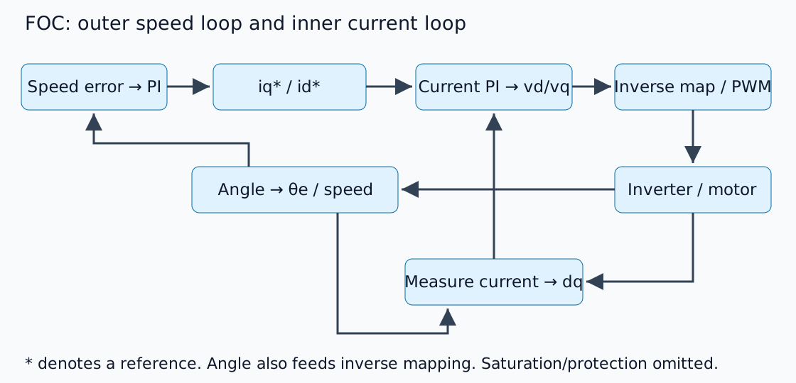
Tanda bintang menunjukkan referensi. Desain loop luar mengasumsikan pelacakan arus yang cukup responsif, tetapi tidak ada rasio bandwidth universal yang dapat mengabaikan dinamika dan penundaan sistem. Bagian 4–5 dari laporan TI PMSM FOC menjelaskan transformasi dan struktur dasarnya. Ini adalah skema penjelasan asli, bukan diagram rangkaian produk.
Melihat tiga fase dalam koordinat berputar
Transformasi Clarke memetakan arus fase ke sumbu αβ stasioner; transformasi Park memutarnya ke sumbu dq yang sejajar dengan fluks rotor. d mengikuti fluks dan q tegak lurus. Ini mengasumsikan urutan nol yang dapat diabaikan dalam fase seimbang dan normalisasi amplitudo/daya yang konsisten.
Untuk motor magnet permukaan yang disederhanakan pada kecepatan yang lebih rendah, konstanta torsi yang didefinisikan dengan tepat memungkinkan Te≈Kt iq. Nilai hipotetis Kt=0,10 N m/A dan iq=3 A menghasilkan 0,30 N m. Ini adalah perhitungan aritmatika berdasarkan konvensi eksplisit, bukan izin untuk mengganti arus RMS fasa secara sembarangan. Sesuaikan konstanta pabrikan dengan definisi transformasi dq.
Sudut listrik berbeda dari sudut mekanik
Dengan p pasang kutub, sudut listrik adalah:
Empat pasang kutub mengubah gerakan mekanik 90° menjadi gerakan listrik 360°. Arah encoder terbalik, offset nol yang salah, atau kutub yang membingungkan dengan pasangan kutub akan memutar arus yang diukur ke sumbu yang salah. Periksa sudut, urutan fasa, dan tanda/offset sensor arus sebelum penyetelan.
id=0 bukan setiap kondisi operasi
Contoh dasar sering kali mengatur referensi sumbu d ke nol. Saliensi magnet internal, operasi torsi maksimum per ampere, dan pelemahan medan kecepatan tinggi memerlukan referensi lain. Peningkatan EMF balik juga dapat mencegah pelacakan arus dalam tegangan bus DC yang tersedia.
Batas arus dan tegangan berbeda. Integrasi melalui penundaan saturasi menunda pemulihan, memotivasi anti-windup. Kegagalan mencapai kecepatan tidak secara otomatis berarti peningkatan kecepatan tidak mencukupi.
Pemeriksaan sebelum implementasi
Ini adalah penjelasan struktur kontrol, bukan pengujian inverter bertenaga. Implementasi harus mempertimbangkan pengaturan waktu pengambilan sampel arus, sinkronisasi PWM, penundaan sudut, dan kondisi proteksi/penghentian. Sebelum mengaktifkan perangkat keras, masukkan vektor dan sudut yang diketahui melalui transformasi dq dan invers, dan verifikasi perjalanan bolak-balik.
Gunakan percobaan PID untuk memeriksa saturasi dan integrasi, kemudian pengenalan reduktor untuk menghubungkan kecepatan motor/beban, torsi, dan inersia.
Komentar
Silakan masuk terlebih dahulu.
Belum ada data.