Contents — find the section you need
Change parameters and verify
Open the panel, then press Run to load Python. You can stop execution and reset parameters. Results are computed on this device. No Python installation is required.
Local execution steps below are optional for reproducing the source results; they are not required for the browser experiment.
The experiment controls are in English.
Explore current coordinates and electrical angle
The panel above is a one-instant coordinate exercise. Supply actual current components in the true rotor frame, mechanical angle, pole-pair count, an electrical-angle error, and a hypothetical torque constant. It constructs balanced phase currents and transforms them back using the supplied estimated angle. These are imposed currents, not current references tracked by a controller. No motor, inverter or local Python is required.
The convention is explicit: α aligns with phase a; β is +90° counterclockwise from α. The true d axis follows rotor flux at θe=p θm, with fixed zero offset 0; q leads d by +90°. Positive angles are counterclockwise. p counts pole pairs, not poles. The display includes unwrapped electrical angle and its modulo-360° direction. Four pole pairs and 90° mechanical angle give 360° electrical angle, equivalent to 0° for the transforms. Changing p here changes the angle mapping only; the separately supplied torque constant stays fixed.
We use amplitude-invariant Clarke normalization with zero sequence fixed to zero. With R(θ)=[[cosθ,−sinθ],[sinθ,cosθ]], first form [iα,iβ]=R(θe)[id,iq]. Generate ia=iα, ib=−iα/2+√3 iβ/2, ic=−iα/2−√3 iβ/2. Thus ia+ib+ic=0. Clarke recovers iα=(2/3)(ia−ib/2−ic/2) and iβ=(ib−ic)/√3. These are instantaneous signed amperes, not phase RMS values. This amplitude normalization is not power invariant: ia²+ib²+ic²=(3/2)(id²+iq²).
The estimated angle is θ̂e=θe+Δθe. Park computes [id̂,iq̂]=R(θ̂e)ᵀ[iα,iβ]. Consequently id̂=id cosΔ+iq sinΔ and iq̂=−id sinΔ+iq cosΔ. At true id=0, iq=3 A and error +90°, the displayed estimated components become id̂=3 A, iq̂≈0. The original phase currents stay the same when only this angle error changes. The diagram shows the same stationary current vector with true and estimated axes; axis-arrow lengths are illustrative and do not encode current. All current scales are shared across A/B.
The inverse uses the same estimated angle: [iα′,iβ′]=R(θ̂e)[id̂,iq̂], then the same inverse Clarke equations. The maximum absolute reconstructed-phase difference should be small even at an incorrect angle. This residual measures algebraic consistency and floating-point roundoff; it cannot establish encoder alignment, sensor accuracy or a working FOC loop. Presets compare +/−90° errors, 180° error, mixed d/q current, zero current, negative q current, and electrical-angle wrapping. A zero vector hides every angle error.
A separate simplified nonsalient PMSM relation gives Te=Kt × true iq. Default Kt=0.10 N m/A and iq=3 A give 0.30 N m. Kt is defined for this amplitude-invariant peak-dq convention and includes the motor-specific conversion; it is not a phase-RMS constant to substitute blindly. The model omits reluctance torque and assumes constant flux. Angle error changes the displayed components but does not change imposed current or modeled torque. A real feedback loop using the wrong angle may change currents; that behavior is not simulated. Nonzero d current is a coordinate example, not a field-weakening or current-limit recommendation.
No PI control, PWM, DC-bus limits, voltage equations, speed dynamics, saliency, field weakening, sensor noise, heating, protection or hardware operation is modeled. Inputs are synthetic teaching assumptions. Use the separate PID Lab for controller behavior and the reducer Lab for mechanical transmission arithmetic.
Reference reviewed 2026-09-20: TI PMSM FOC report, sections 4–5. This exercise states its normalization and sign convention directly; it does not reproduce the report's motor-control implementation.
구동 장치는 기계적 속도를 직접 설정할 수 없습니다. 전압을 생성하고, 권선 전류와 자기장을 변화시켜 토크를 발생시키고, 이 토크로 회전 속도를 변화시킵니다. 필드 지향 제어(FOC)는 회전 자기장에 맞춰 정렬된 좌표계를 사용하여 전류 제어를 단순화합니다. 이 소개에서는 영구 자석 동기 모터(PMSM)를 중심으로 설명합니다.
전류, 토크, 속도 분리
간단한 기계적 방정식은 다음과 같습니다.
여기서 J는 관성 모멘트[kg m²], ω는 기계적 각속도[rad/s], Te는 전자기 토크[N m], TL은 부하 토크[N m], B는 점성 저항[N m s/rad]입니다. 관성이나 부하가 클 경우 토크가 크면 속도를 즉시 변화시킬 필요가 없습니다. 일정한 속도를 유지하는 데에도 토크가 필요할 수 있습니다.
외부 속도 루프, 내부 전류 루프
속도 오차는 PI 컨트롤러를 구동하여 토크에 따른 전류 기준값을 생성합니다. 내부 전류 PI 컨트롤러는 전압 기준값을 생성하고, PWM은 인버터 스위칭을 통해 이를 구현합니다.
측정 전류 및 각도 피드백을 사용하는 FOC 속도/전류 루프
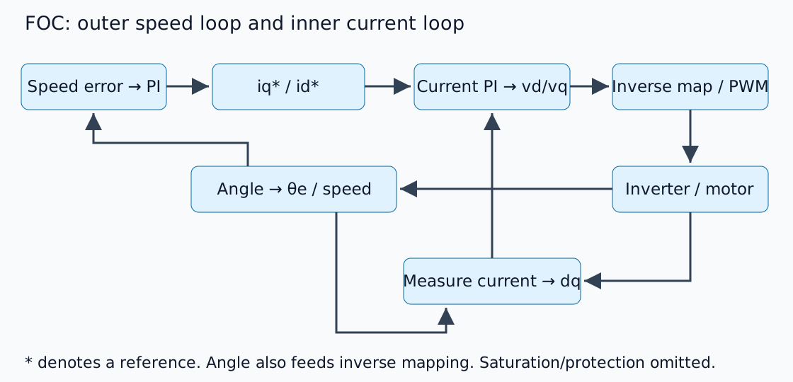
별표는 참조를 나타냅니다. 외부 루프 설계는 충분히 반응하는 전류 추적을 가정하지만, 보편적인 대역폭 비율은 플랜트 동역학과 지연을 무시할 수 없습니다. TI PMSM FOC 보고서의 4~5절에서 변환 및 기본 구조를 설명합니다. 이것은 제품 회로도가 아닌 설명용 개략도입니다.
회전 좌표계에서 3상 보기
클라크 변환은 상 전류를 고정된 αβ 축에 매핑하고, 파크 변환은 이를 회전자 자속에 정렬된 dq 축으로 회전시킵니다. d는 자속을 따르고 q는 자속에 수직입니다. 이는 평형 위상에서 영순위가 무시할 수 있고 진폭/전력 정규화가 일관적이라고 가정합니다.
저속에서 단순화된 표면 자석 모터의 경우, 적절하게 정의된 토크 상수를 사용하면 Te≈Kt iq가 가능합니다. 가상의 Kt=0.10 N m/A 및 iq=3 A인 경우 0.30 N m이 됩니다. 이는 명시적인 규칙에 따른 계산이며, 위상 RMS 전류를 임의로 대체할 수 있다는 의미가 아닙니다. 제조사 상수를 dq 변환 정의와 일치시키십시오.
전기각은 기계각과 다릅니다
p극쌍의 경우 전기각은 다음과 같습니다.
4극쌍은 90°의 기계 운동을 360°의 전기 운동으로 변환합니다. 엔코더 방향 반전, 잘못된 영점 오프셋 또는 극과 극쌍을 혼동하면 측정 전류가 잘못된 축으로 회전합니다. 조정하기 전에 각도, 위상 순서 및 전류 센서 부호/오프셋을 확인하십시오.
id=0이 모든 작동 조건에 적합한 것은 아닙니다
일반적인 예에서는 d축 기준값을 0으로 설정합니다. 내부 자석 돌극성, 최대 토크/암페어 작동 및 고속 자계 약화에는 다른 기준값이 필요합니다. 역기전력을 증가시키면 사용 가능한 DC 버스 전압 내에서 전류 추적을 방지할 수 있습니다.
전류와 전압 제한은 별개입니다. 포화 구간을 통과하는 적분은 회복을 지연시키므로 안티와인드업이 필요합니다. 목표 속도에 도달하지 못했다고 해서 속도 이득이 부족한 것은 아닙니다.
구현 전 확인 사항
이것은 제어 구조에 대한 설명이며, 전력 인버터 테스트가 아닙니다. 구현 시에는 전류 샘플링 타이밍, PWM 동기화, 각도 지연 및 보호/정지 조건을 고려해야 합니다. 하드웨어에 전원을 공급하기 전에 알려진 벡터와 각도를 dq 및 역변환을 통해 입력하고 왕복을 검증하십시오.
포화 및 적분에 대해서는 PID 실험을 참조하고, 모터/부하 속도, 토크 및 관성 간의 관계에 대해서는 감속기 소개를 참조하십시오.
댓글
먼저 로그인해 주세요.
아직 데이터가 없습니다.