Contents — find the section you need
Change parameters and verify
Open the panel, then press Run to load Python. You can stop execution and reset parameters. Results are computed on this device. No Python installation is required.
Local execution steps below are optional for reproducing the source results; they are not required for the browser experiment.
The experiment controls are in English.
Explore ratio, mechanical power and reflected inertia
Use the panel above to vary a hypothetical reducer's speed ratio, imposed input speed and torque, assumed motoring efficiency, and load inertia. No local Python is needed. These are arithmetic examples, not measurements, product ratings or a mechanism selector. The original mechanism comparison remains below.
N is the positive magnitude of input/output speed ratio. Input speed n is in revolutions per minute and ωin=2πn/60 rad/s. Under steady positive motoring with constant assumed efficiency η, the model computes nout=n/N, Tout=η N Tin, Pin=Tin ωin, Pout=η Pin and Ploss=(1−η) Pin. It also satisfies Pout=Tout ωout with ωout=ωin/N. All speed and torque values are magnitudes: no shaft direction is inferred from N. Both input speed and torque are prescribed; a real motor may not sustain that pair.
At 3,000 rpm, 0.20 N m, N=50 and η=0.8, output is 60 rpm and 8 N m. Mechanical input is about 62.832 W, output 50.265 W and loss 12.566 W. Doubling N halves output speed and doubles output torque while keeping the assumed input and efficiency fixed. Power does not increase. Changing η changes torque and output/loss power but leaves the kinematic speed ratio unchanged. η=1 is an ideal lossless reference, not a realistic efficiency claim. The chosen control bounds keep speed and torque positive; they do not cover standstill, breakaway friction or backdriving.
The separate ideal rigid-transmission relation is Jload,ref=Jload/N². For the assumed 0.020 kg m² load and N=50, this is 0.000008 kg m² at the input. It follows by equating ½ Jload ωout² and ½ Jload,ref ωin². Efficiency is not inserted in this inertial equivalence. The model omits motor rotor and gearbox inertia. Load inertia changes only this separate result; no acceleration, acceleration torque or transient response is simulated. Zero load inertia is an ideal reference, not proof that a drive has no inertia.
Try half/double ratio, unity ratio, lower efficiency, the ideal lossless case, higher speed, higher torque and zero load inertia. The speed, torque and power bars use separate units and scales, shared across A/B for each quantity. Blue is mechanical input, teal output; the power split adds brown loss. Exact computed values remain in the accessible metrics/table even when a bar is very small. Reflected inertia is shown numerically to avoid hiding the square-law change in a tiny bar. Displayed values are rounded.
Constant efficiency is supplied, not predicted from ratio, speed, load, temperature or mechanism. Loss power is an accounting difference, not a temperature estimate or electrical motor loss. There is no tooth geometry, stage count, backlash, elasticity, torque-speed curve, reverse efficiency, bearing load, thermal limit, life estimate or allowable torque. These bounds are teaching choices. Do not treat a calculated torque as a reducer's load rating or infer backdrivability from N and η.
References reviewed 2026-09-20: Oriental Motor on torque and load inertia through gearing and maxon gearhead selection. The browser uses generic scalar relations, without adopting any manufacturer's product specifications. Continue below for planetary, strain-wave and cycloidal mechanisms; motor FOC discusses how motor torque is controlled.
감속기는 고속 모터와 저속 로봇 관절을 연결하여 속도를 토크로 교환하는 장치입니다. 이 글에서는 고정비 유성 기어, 스트레인웨이브 기어, 사이클로이드 기어 메커니즘을 비교합니다. 메커니즘 이름만으로는 정확도나 수명을 판단할 수 없습니다.
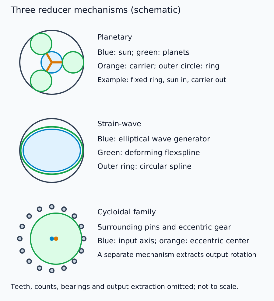
유성 기어, 스트레인웨이브 기어, 사이클로이드 기어 부재의 개략도; 치형 및 출력 추출은 생략
속도, 토크 및 반사 관성 계산
입력/출력 속도비의 크기를 N, 모터 구동 효율을 η라고 합시다. 정상 작동 시 다음 관계식이 성립합니다.
마지막 관계식은 이상적인 강체 변속기를 가정합니다. 기어박스의 관성, 탄성 및 마찰은 추가적인 영향 요소입니다. 역회전 효율은 η와 같을 필요는 없습니다.
가상의 입력 3,000 rpm 및 0.20 N·m에 대해 N=50, η=0.8이면 60 rpm 및 약 8 N·m의 토크가 발생합니다. 기계적 입력 전력은 약 62.8W이고 출력은 약 50.3W입니다. 토크 증폭은 에너지를 생성하지 않습니다. 이는 산술적 가정이며, 실제 제품 정격이 아닙니다.
유성 기어
태양 기어, 유성 기어, 내부 링 기어 및 캐리어 기어가 메커니즘을 구성합니다. 고정, 입력 및 출력 부재가 기어비와 방향을 결정합니다. 고정 링 기어, 태양 기어 입력 및 캐리어 출력으로 구성된 단순 단에서 기어비는 1 + 링 기어 톱니 수 / 태양 기어 톱니 수입니다.
60개의 톱니를 가진 링 기어, 20개의 톱니를 가진 태양 기어, 20개의 톱니를 가진 유성 기어는 이러한 구성에서 기어비 4를 제공합니다. 공식을 사용할 때 부재 제약 조건을 생략하지 마십시오. 다단 기어는 효율, 크기 및 강성을 변경하면서 기어비를 높일 수 있습니다. HDS 제품 목록에는 정밀 유성 기어 및 스트레인 웨이브 제품이 모두 포함되어 있으며, 제조업체는 특정 메커니즘에만 국한되지 않습니다.
변형파 기어
타원형 파동 발생기, 유연한 플렉스 스플라인, 그리고 강성 원형 스플라인이 맞물림 영역을 움직입니다. HDS 작동 원리는 이러한 요소들과 톱니 수 차이를 설명합니다.
원형 스플라인이 고정되고 파동 발생기가 입력, 플렉스 스플라인이 출력으로 구성된 경우, 200개의 플렉스 스플라인 톱니와 202개의 원형 스플라인 톱니는 입력 회전당 -2/200의 출력 회전을 생성합니다. 즉, 기어비 크기는 100입니다. 탄성 변형은 의도적인 것이므로 조립, 윤활 및 하중 조건이 중요합니다.
사이클로이드 메커니즘
편심 운동하는 기어/디스크가 주변 핀 또는 관련 요소와 맞물려 톱니 수 차이로부터 감소된 회전을 생성합니다. 출력 메커니즘은 전체 편심 운동을 전달하지 않고 회전을 추출합니다. 모든 제품이 동일한 단일 단계 구조를 갖는 것은 아닙니다.
나브테스코의 RV 원리는 초기 스퍼 기어 단계와 두 번째 편심 단계를 설명합니다. RV는 제품군이며, 모든 사이클로이드 감속기를 지칭하는 동의어가 아닙니다. 개별 모델 정격과 메커니즘에 대한 이해는 별개입니다.
공통 축 비교
| 축 | 점검 사항 | 일반적인 오류 |
|---|---|---|
| 속도/토크 | 정격, 가속 피크, 비상 하중 및 작동 시간 | 짧은 피크를 연속 정격으로 간주 |
| 백래시/손실 운동 | 시험 하중 및 정의 | 무부하 간극과 역회전 동작의 혼동 |
| 비틀림 강성 | 하중 대 처짐 | 백래시가 낮으면 처짐이 없다고 가정 |
| 지지/장착 | 출력 베어링, 모멘트 및 정렬 | 기어 부품만으로 외부 하중을 지지할 것으로 예상 |
| 마찰/역구동 | 온도, 속도, 효율 및 이탈 토크 | 접촉력 또는 수동 조작의 오판 |
| 수명/서비스 | 부하 이력, 윤활, 밀봉 및 환경 | 동일 비율이 동일하다고 가정하는 것은 수명이 같다는 것을 의미 |
정밀 위치 지정, 접촉 작업 및 빠른 이송은 각 축의 우선순위를 결정합니다. 먼저 부하 이력과 장착 방식을 정의한 다음, 해당 조건에서 실제 모델 문서를 비교하십시오. 여기에는 보편적인 메커니즘 순위가 없습니다.
제어 및 회사 연구 연결
출력 탄성 및 마찰로 인해 모터 측 엔코더가 부하 상태를 완벽하게 설명하지 못할 수 있습니다. 비율이 증가하면 속도 범위, 반사 관성 및 역구동 가능성과 해상도가 변경됩니다. 이러한 효과를 모터 FOC에서 생성되는 토크와 연결하십시오.
다음으로, 감속기 제조업체 연구는 공급 경계(구성 요소, 베어링 지지 장치 및 액추에이터)를 비교합니다.
댓글
먼저 로그인해 주세요.
아직 데이터가 없습니다.