Contents — find the section you need
Change parameters and verify
Open the panel, then press Run to load Python. You can stop execution and reset parameters. Results are computed on this device. No Python installation is required.
Local execution steps below are optional for reproducing the source results; they are not required for the browser experiment.
The experiment controls are in English.
Explore ratio, mechanical power and reflected inertia
Use the panel above to vary a hypothetical reducer's speed ratio, imposed input speed and torque, assumed motoring efficiency, and load inertia. No local Python is needed. These are arithmetic examples, not measurements, product ratings or a mechanism selector. The original mechanism comparison remains below.
N is the positive magnitude of input/output speed ratio. Input speed n is in revolutions per minute and ωin=2πn/60 rad/s. Under steady positive motoring with constant assumed efficiency η, the model computes nout=n/N, Tout=η N Tin, Pin=Tin ωin, Pout=η Pin and Ploss=(1−η) Pin. It also satisfies Pout=Tout ωout with ωout=ωin/N. All speed and torque values are magnitudes: no shaft direction is inferred from N. Both input speed and torque are prescribed; a real motor may not sustain that pair.
At 3,000 rpm, 0.20 N m, N=50 and η=0.8, output is 60 rpm and 8 N m. Mechanical input is about 62.832 W, output 50.265 W and loss 12.566 W. Doubling N halves output speed and doubles output torque while keeping the assumed input and efficiency fixed. Power does not increase. Changing η changes torque and output/loss power but leaves the kinematic speed ratio unchanged. η=1 is an ideal lossless reference, not a realistic efficiency claim. The chosen control bounds keep speed and torque positive; they do not cover standstill, breakaway friction or backdriving.
The separate ideal rigid-transmission relation is Jload,ref=Jload/N². For the assumed 0.020 kg m² load and N=50, this is 0.000008 kg m² at the input. It follows by equating ½ Jload ωout² and ½ Jload,ref ωin². Efficiency is not inserted in this inertial equivalence. The model omits motor rotor and gearbox inertia. Load inertia changes only this separate result; no acceleration, acceleration torque or transient response is simulated. Zero load inertia is an ideal reference, not proof that a drive has no inertia.
Try half/double ratio, unity ratio, lower efficiency, the ideal lossless case, higher speed, higher torque and zero load inertia. The speed, torque and power bars use separate units and scales, shared across A/B for each quantity. Blue is mechanical input, teal output; the power split adds brown loss. Exact computed values remain in the accessible metrics/table even when a bar is very small. Reflected inertia is shown numerically to avoid hiding the square-law change in a tiny bar. Displayed values are rounded.
Constant efficiency is supplied, not predicted from ratio, speed, load, temperature or mechanism. Loss power is an accounting difference, not a temperature estimate or electrical motor loss. There is no tooth geometry, stage count, backlash, elasticity, torque-speed curve, reverse efficiency, bearing load, thermal limit, life estimate or allowable torque. These bounds are teaching choices. Do not treat a calculated torque as a reducer's load rating or infer backdrivability from N and η.
References reviewed 2026-09-20: Oriental Motor on torque and load inertia through gearing and maxon gearhead selection. The browser uses generic scalar relations, without adopting any manufacturer's product specifications. Continue below for planetary, strain-wave and cycloidal mechanisms; motor FOC discusses how motor torque is controlled.
减速器将高速电机连接到低速机器人关节,以速度换取扭矩。本文比较了固定传动比的行星齿轮机构、应变波机构和摆线机构。机构名称本身并不能代表精度或寿命。
计算速度、扭矩和反射惯量
设 N 为输入/输出速度比,η 为电机效率。在稳定运行状态下:
最后一个公式假设为理想刚性传动。齿轮箱惯性、弹性和摩擦力仍然是附加影响因素。反向驱动效率不一定等于 η。
假设输入转速为 3000 rpm,扭矩为 0.20 N·m,则 N=50 和 η=0.8 时,转速为 60 rpm,扭矩约为 8 N·m。机械输入功率约为 62.8 W;输出功率约为 50.3 W。扭矩倍增并不产生能量。这些是算术假设,并非选定的产品额定值。
行星齿轮机构
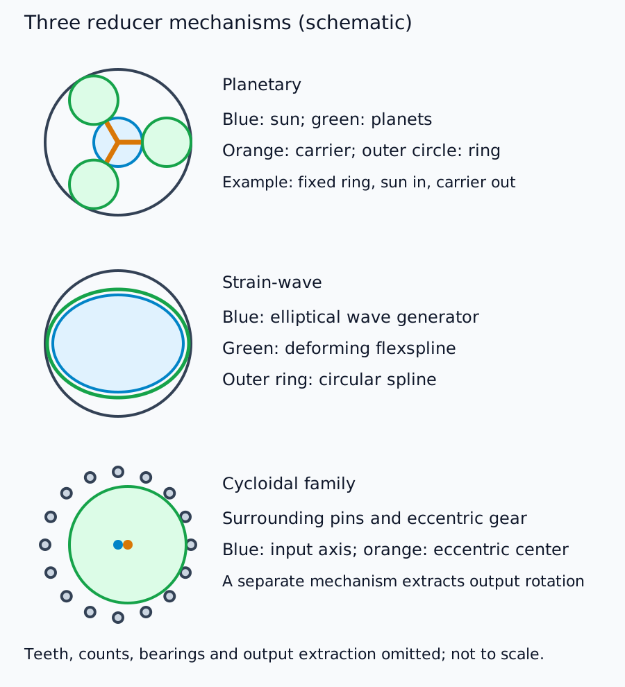
该机构由太阳轮、行星齿轮、内环和行星架组成。固定部件、输入部件和输出部件决定传动比和方向。在一个简单的级中,内环固定,太阳轮为输入,行星架为输出,传动比为 1 + 内环齿数 / 太阳轮齿数。
在这种情况下,一个 60 齿的内环、20 齿的太阳轮和 20 齿的行星齿轮的传动比为 4。使用该公式时,请勿忽略部件约束。多级结构可以提高传动比,但会改变效率、尺寸和刚度。HDS 产品列表包含精密行星齿轮和应变波齿轮产品;制造商不一定只生产一种机构。
应变波齿轮机构
椭圆波发生器、柔性花键和刚性圆花键用于移动啮合区域。 HDS 工作原理解释了这些元件以及齿数差异。
在圆花键固定、波形发生器输入和柔性花键输出的情况下,200 个柔性花键齿和 202 个圆花键齿每输入一圈,输出旋转 -2/200 圈:比值约为 100。弹性变形是人为设计的,因此装配、润滑和负载条件至关重要。
摆线机构
偏心运动的齿轮/圆盘与周围的销或相关元件啮合,利用齿数差异实现减速旋转。输出机构提取旋转,但不传递完整的偏心运动。并非所有产品都采用相同的单级结构。
Nabtesco 的 RV 原理描述了初始正齿轮级和第二偏心级。RV 是一个产品系列,并非所有摆线减速器的同义词。对机构的理解与对单个型号的额定值的理解是分开的。
常见轴的比较
| 轴 | 检查内容 | 常见错误 |
|---|---|---|
| 速度/扭矩 | 额定值、加速度峰值、紧急负载和工作状态 | 将短峰值视为连续额定值 |
| 齿隙/空行程 | 测试负载及其定义 | 混淆空载间隙和反转行为 |
| 扭转刚度 | 负载与挠度的关系 | 假设低齿隙意味着无挠度 |
| 支撑/安装 | 输出轴承、力矩和对准 | 仅依靠齿轮部件来承受外部负载 |
| 摩擦/反驱动 | 温度、速度、效率和启动扭矩 | 误判接触力或手动操作 |
| 寿命/使用 | 负载历史、润滑、密封和环境 | 假设相同的传动比意味着相同的寿命 |
精密定位、接触任务和快速运输对轴的优先级要求不同。首先定义负载历史和安装方式,然后在这些条件下比较实际型号文档。此处没有通用的机构排名。
连接控制与公司研究
输出弹性和摩擦意味着电机侧编码器可能无法完全描述负载状态。提高变速比会改变速度范围、反射惯量和反驱动能力以及分辨率。将这些影响与电机 FOC 产生的扭矩联系起来。
接下来,减速器制造商研究比较了供应范围:组件、轴承支撑单元和执行器。
评论
请先登录。
暂无数据。