Contents — find the section you need
Change parameters and verify
Open the panel, then press Run to load Python. You can stop execution and reset parameters. Results are computed on this device. No Python installation is required.
Local execution steps below are optional for reproducing the source results; they are not required for the browser experiment.
The experiment controls are in English.
Explore current coordinates and electrical angle
The panel above is a one-instant coordinate exercise. Supply actual current components in the true rotor frame, mechanical angle, pole-pair count, an electrical-angle error, and a hypothetical torque constant. It constructs balanced phase currents and transforms them back using the supplied estimated angle. These are imposed currents, not current references tracked by a controller. No motor, inverter or local Python is required.
The convention is explicit: α aligns with phase a; β is +90° counterclockwise from α. The true d axis follows rotor flux at θe=p θm, with fixed zero offset 0; q leads d by +90°. Positive angles are counterclockwise. p counts pole pairs, not poles. The display includes unwrapped electrical angle and its modulo-360° direction. Four pole pairs and 90° mechanical angle give 360° electrical angle, equivalent to 0° for the transforms. Changing p here changes the angle mapping only; the separately supplied torque constant stays fixed.
We use amplitude-invariant Clarke normalization with zero sequence fixed to zero. With R(θ)=[[cosθ,−sinθ],[sinθ,cosθ]], first form [iα,iβ]=R(θe)[id,iq]. Generate ia=iα, ib=−iα/2+√3 iβ/2, ic=−iα/2−√3 iβ/2. Thus ia+ib+ic=0. Clarke recovers iα=(2/3)(ia−ib/2−ic/2) and iβ=(ib−ic)/√3. These are instantaneous signed amperes, not phase RMS values. This amplitude normalization is not power invariant: ia²+ib²+ic²=(3/2)(id²+iq²).
The estimated angle is θ̂e=θe+Δθe. Park computes [id̂,iq̂]=R(θ̂e)ᵀ[iα,iβ]. Consequently id̂=id cosΔ+iq sinΔ and iq̂=−id sinΔ+iq cosΔ. At true id=0, iq=3 A and error +90°, the displayed estimated components become id̂=3 A, iq̂≈0. The original phase currents stay the same when only this angle error changes. The diagram shows the same stationary current vector with true and estimated axes; axis-arrow lengths are illustrative and do not encode current. All current scales are shared across A/B.
The inverse uses the same estimated angle: [iα′,iβ′]=R(θ̂e)[id̂,iq̂], then the same inverse Clarke equations. The maximum absolute reconstructed-phase difference should be small even at an incorrect angle. This residual measures algebraic consistency and floating-point roundoff; it cannot establish encoder alignment, sensor accuracy or a working FOC loop. Presets compare +/−90° errors, 180° error, mixed d/q current, zero current, negative q current, and electrical-angle wrapping. A zero vector hides every angle error.
A separate simplified nonsalient PMSM relation gives Te=Kt × true iq. Default Kt=0.10 N m/A and iq=3 A give 0.30 N m. Kt is defined for this amplitude-invariant peak-dq convention and includes the motor-specific conversion; it is not a phase-RMS constant to substitute blindly. The model omits reluctance torque and assumes constant flux. Angle error changes the displayed components but does not change imposed current or modeled torque. A real feedback loop using the wrong angle may change currents; that behavior is not simulated. Nonzero d current is a coordinate example, not a field-weakening or current-limit recommendation.
No PI control, PWM, DC-bus limits, voltage equations, speed dynamics, saliency, field weakening, sensor noise, heating, protection or hardware operation is modeled. Inputs are synthetic teaching assumptions. Use the separate PID Lab for controller behavior and the reducer Lab for mechanical transmission arithmetic.
Reference reviewed 2026-09-20: TI PMSM FOC report, sections 4–5. This exercise states its normalization and sign convention directly; it does not reproduce the report's motor-control implementation.
एक ड्राइव सीधे यांत्रिक गति निर्धारित नहीं कर सकती। यह वोल्टेज उत्पन्न करती है, वाइंडिंग करंट और चुंबकीय क्षेत्र को बदलती है, और फिर टॉर्क उत्पन्न करती है जो घूर्णन को बदलता है। फील्ड-ओरिएंटेड कंट्रोल (FOC) घूर्णन क्षेत्र के साथ संरेखित निर्देशांकों का उपयोग करके करंट नियंत्रण को सरल बनाता है। यह परिचय एक स्थायी-चुंबक सिंक्रोनस मोटर (PMSM) पर केंद्रित है।
अलग-अलग करंट, टॉर्क और गति
एक सरलीकृत यांत्रिक समीकरण इस प्रकार है:
J जड़त्व [kg m²], ω यांत्रिक कोणीय वेग [rad/s], Te विद्युत चुम्बकीय टॉर्क [N m], TL लोड टॉर्क [N m] और B श्यान प्रतिरोध [N m s/rad] है। अधिक टॉर्क से पर्याप्त जड़त्व या भार के तहत गति में तुरंत परिवर्तन होना आवश्यक नहीं है। स्थिर गति बनाए रखने के लिए भी टॉर्क की आवश्यकता हो सकती है।
बाहरी गति लूप, आंतरिक करंट लूप
गति त्रुटि एक PI नियंत्रक को संचालित करती है जो टॉर्क-संबंधी करंट संदर्भ उत्पन्न करता है। आंतरिक करंट PI नियंत्रक वोल्टेज संदर्भ उत्पन्न करते हैं; PWM उन्हें इन्वर्टर स्विचिंग के माध्यम से साकार करता है।
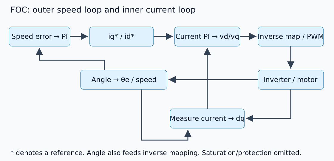
एक तारांकन चिह्न संदर्भ को दर्शाता है। बाहरी लूप डिज़ाइन पर्याप्त रूप से प्रतिक्रियाशील धारा ट्रैकिंग मानता है, लेकिन कोई भी सार्वभौमिक बैंडविड्थ अनुपात प्लांट की गतिशीलता और विलंब को अनदेखा नहीं कर सकता है। TI PMSM FOC रिपोर्ट के खंड 4-5 रूपांतरणों और मूल संरचना की व्याख्या करते हैं। यह एक मूल व्याख्यात्मक आरेख है, उत्पाद सर्किट आरेख नहीं।
घूर्णन निर्देशांक में तीन चरणों को देखें
क्लार्क रूपांतरण चरण धाराओं को स्थिर αβ अक्षों पर मैप करता है; पार्क रूपांतरण उन्हें रोटर-फ्लक्स-संरेखित dq अक्षों में घुमाता है। d फ्लक्स का अनुसरण करता है और q लंबवत है। यह संतुलित चरणों में नगण्य शून्य अनुक्रम और सुसंगत आयाम/शक्ति सामान्यीकरण मानता है।
कम गति पर एक सरलीकृत सतह-चुंबक मोटर के लिए, एक उपयुक्त रूप से परिभाषित टॉर्क स्थिरांक Te≈Kt iq की अनुमति देता है। एक काल्पनिक Kt=0.10 N m/A और iq=3 A से 0.30 N m प्राप्त होता है। यह एक स्पष्ट नियम के अंतर्गत अंकगणित है, न कि चरण RMS धारा को मनमाने ढंग से प्रतिस्थापित करने की अनुमति। निर्माता स्थिरांकों को dq रूपांतरण परिभाषा से मिलाएं।
विद्युत कोण यांत्रिक कोण से भिन्न होता है
p ध्रुव युग्मों के साथ, विद्युत कोण इस प्रकार है:
चार ध्रुव युग्म 90° यांत्रिक गति को 360° विद्युत गति में परिवर्तित करते हैं। एनकोडर की दिशा उलट जाने, शून्य ऑफ़सेट गलत होने या ध्रुव युग्मों के साथ ध्रुवों के भ्रमित होने से मापी गई धाराएँ गलत अक्षों में घूम जाती हैं। ट्यूनिंग से पहले कोण, चरण क्रम और धारा-संवेदक संकेतों/ऑफ़सेट की जाँच करें।
id=0 हर परिचालन स्थिति नहीं है
एक बुनियादी उदाहरण अक्सर d-अक्ष संदर्भ को शून्य पर सेट करता है। आंतरिक-चुंबक की प्रमुखता, प्रति एम्पीयर अधिकतम टॉर्क संचालन और उच्च गति क्षेत्र कमजोर होने के लिए अन्य संदर्भों की आवश्यकता होती है। बैक ईएमएफ में वृद्धि उपलब्ध डीसी-बस वोल्टेज के भीतर करंट ट्रैकिंग को भी बाधित कर सकती है।
करंट और वोल्टेज की सीमाएँ अलग-अलग होती हैं। संतृप्ति के माध्यम से एकीकरण से रिकवरी में देरी होती है, जिससे एंटी-विंडअप की आवश्यकता होती है। गति प्राप्त करने में विफलता का अर्थ यह नहीं है कि गति लाभ अपर्याप्त है।
कार्यान्वयन से पहले जाँच
यह एक नियंत्रण संरचना का स्पष्टीकरण है, न कि पावर्ड इन्वर्टर का परीक्षण। कार्यान्वयन में करंट-सैंपलिंग टाइमिंग, पीडब्ल्यूएम सिंक्रोनाइज़ेशन, एंगल डिले और प्रोटेक्शन/स्टॉप स्थितियों पर विचार करना आवश्यक है। हार्डवेयर को सक्रिय करने से पहले, ज्ञात वैक्टर और कोणों को डीक्यू और व्युत्क्रम रूपांतरणों के माध्यम से प्रवाहित करें और राउंड ट्रिप की पुष्टि करें।
संतृप्ति और एकीकरण की जाँच के लिए पीआईडी प्रयोग का उपयोग करें, फिर मोटर/लोड गति, टॉर्क और जड़त्व को जोड़ने के लिए रिड्यूसर परिचय का उपयोग करें।
टिप्पणियाँ
पहले लॉग इन करें।
अभी कोई डेटा नहीं है।