Contents — find the section you need
Background and reading guide
Background Basic force, motion and energy terminology; use the linked background explanations.
Fundamentals · Explanations of principles, structure and trade-offs.
A bulldozer's job is less "scooping up earth" than "pushing, leveling, and compacting" it. It piles soil onto the front blade while transmitting large traction force to the ground through its crawlers, shaping the height and slope of a design surface. From the operator's seat it can look like simple lever operation, but on the actual machine the engine, hydraulic pumps, travel motors, crawlers, blade cylinders, GNSS, and IMU all form a single control system.
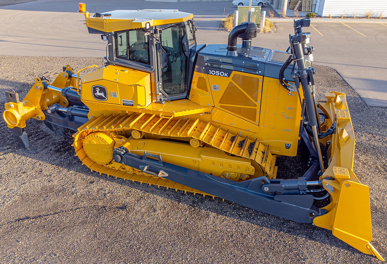 Bulldozer in the field
Image: Bulldozer 2 (Wikideas1, CC0), Wikimedia Commons. A representative crawler, blade, and hydraulic-cylinder layout, not one of the Komatsu or Caterpillar models discussed in the text.

0. 30-Second Summary
- Crawlers have a large contact area and resist sinking in soft ground. Driving the left and right sides independently also allows a pivot turn by stopping one side.
- The blade's cutting-edge position is derived via forward kinematics from body attitude, blade angle, cylinder length, and GNSS/IMU. ICT construction is what displays and controls the difference from the design surface down to a few centimeters or less.
- As resistance to pushing soil increases, engine output, hydraulic pressure, and crawler slip ratio all approach their limits simultaneously. Simply lowering the blade doesn't mean advancing faster.
- Komatsu's ICT-compatible dozers and Caterpillar's D6 XE electric drivetrain are current examples aiming simultaneously at automatic blade-tip control and fuel efficiency/productivity. Confirm model, equipment, and regional spec with official materials.
- Autonomous leveling research fuses blade IMU, body RTK-GNSS, hydraulic pressure, and soil-volume models via EKF/MPC or machine learning. Changes in soil quality and safety monitoring remain difficult to the end.
1. Three Balances That Determine the Work
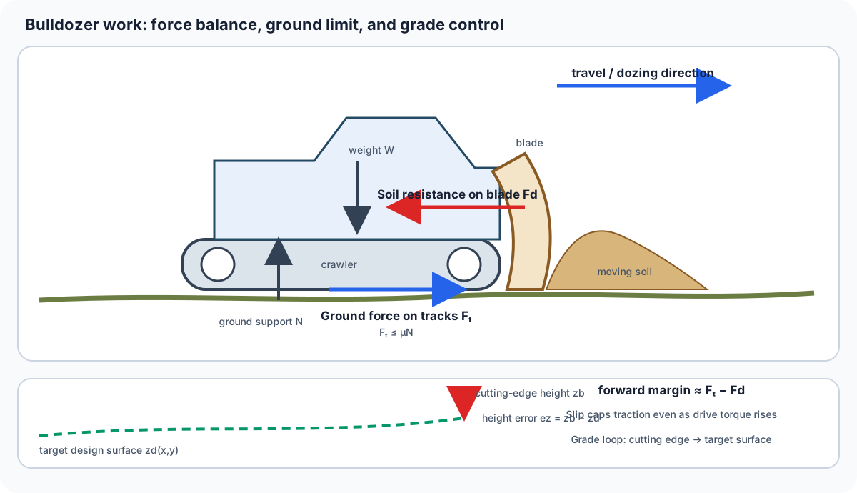
Figure 1 — Taking travel as positive, the available forward margin is approximately F_t-F_d, while ground conditions limit F_t. Height error e_z is not a third force; it is the control variable used to bring the cutting edge onto the design surface.
Ground Pressure
Let body weight be W and the total ground-contact area of the left and right crawlers be A_c. Then average ground pressure is
The lower the ground pressure, the less prone to sinking in soft ground, but the crawlers become longer and heavier, increasing turning resistance and transport weight. Track width and shoe shape — low-ground-pressure specs for wetlands, wear-resistant shoes for rock — are chosen to match the work site.
Traction and Slip
The maximum traction force a crawler can transmit to the ground is, in simplified form, determined by friction coefficient \mu and normal load N as
Even raising hydraulic motor torque doesn't help if the soil can't be sheared — the crawler simply spins. Slip ratio s, using theoretical speed v_0 and actual speed v, can be expressed as
Because the optimal slip ratio changes with soil type and moisture content, engine speed, the travel pump, and blade load are coordinately controlled.
Blade Resistance
The resistance acting on the blade's cutting edge is the sum of soil shear, friction, pushing up soil clods, and friction against the blade's front face. It changes greatly with the soil's internal friction angle, cohesion, moisture content, and cut depth. Accurately tracking the design surface requires not just position control but also load control, which estimates load from hydraulic pressure and limits cut depth.
2. Blade Geometry and Hydraulics
The blade changes lift (up/down), pitch (fore/aft), and tilt (left/right) via hydraulic cylinders. Shapes such as straight, U, semi-U, and angle differ by model, changing the balance between soil volume carried and pushing resistance. Letting the blade reference point in body coordinates be \mathbf{p}_B, body attitude be rotation matrix R_{WB}, and position be \mathbf{t}_{WB}, the cutting-edge position is
q is the joint angle back-calculated from cylinder length. A hydraulic cylinder's thrust is the product F=\Delta pA of differential pressure \Delta p and piston area A, but because the linkage's moment arm changes with attitude, the force transmitted to the cutting edge isn't constant even at the same pressure.
3. ICT Construction: Turning the Design Surface Into "Ground Inside the Screen"
On site, a triangular-mesh design surface is built from point-cloud survey data or drawings, and the machine's current position and blade cutting edge are compared against that surface. RTK-GNSS provides the body's absolute position, two antennas or an IMU provide attitude, and cylinder stroke provides the blade's relative angle. The operator's in-cab screen displays "how many more cm to lower" and "which direction to move."
In a research example, two RTK-GNSS units combined with body and blade IMUs were used to estimate blade cutting-edge position on an actual machine, with a reported error verified to within 30 mm. This doesn't mean the machine became fully unmanned — it's the measurement foundation for progressing from machine guidance that assists a skilled operator toward automatic blade control.
As a current product example, Komatsu's ICT-construction-compatible dozers (the D61/D65 series' i-series, etc.) take a configuration integrating GNSS antennas, inertial sensors, cylinder stroke, and design data. Caterpillar's D6 XE is one example of a dozer line adopting electric drive, converting engine power to electric generation and drive, aiming at low-speed responsiveness and fuel efficiency. Because features vary by standard equipment vs. options, sales region, and software contract in both cases, purchase decisions should cross-check official spec sheets against actual construction conditions.
4. Feedback in Blade Control
Let the design surface's height be z_d(x,y) and the estimated cutting-edge height be z_b, forming error e_z=z_b-z_d. With simple proportional control, the cylinder speed command becomes
However, while pushing soil, the lower the blade goes, the more resistance increases, decelerating the body and changing its attitude. So model predictive control (MPC), which includes body speed, pitch angle, hydraulic pressure, and crawler slip ratio in its state, is used. This is because it can simultaneously handle input constraints (cylinder speed/pressure/engine output) and safety constraints (distance to workers/tip-over margin).
The minimal implementation loop is as follows.
- Estimate body attitude from GNSS/IMU, and blade attitude from encoders/stroke.
- Interpolate the design-surface mesh to the current position and compute height/slope error against the cutting edge.
- Estimate soil load and slip from pressure and crawler speed.
- Generate a target blade speed and issue a constrained command to the hydraulic valve.
- Evaluate the residual via as-built survey and update the model's soil parameters.
5. Where Electrification and Autonomy Meet
Because a dozer spends a long time at low speed and high traction, the benefits of electric drive show up readily. A motor can deliver high torque from a standstill, simplifies the mechanical transmission, and can return downhill energy to the battery via regeneration. On the other hand, battery weight, charging equipment, cold-weather capacity, durability against dust/water/impact, and thermal design during long work sessions are challenges. Design also differs depending on whether the hydraulic blade is replaced with electric cylinders, or whether the hydraulic pump itself is driven by an electric motor.
In autonomy, the "cutting pass" that pushes soil volume and the "haul pass" that dumps soil are planned separately. LiDAR or stereo cameras recognize obstacles and terrain, and where GNSS is blocked, an IMU and body motion model interpolate over short periods. Research since 2025 has reported self-localization using blade/hydraulic-pressure/body-vibration as features, and data-driven blade control learned in simulation. However, fail-safes for soil types not in the training data, wet clay, buried objects, and unexpected worker movement must be designed together with on-site rules.
6. Summary
The core of a bulldozer lies in simultaneously achieving traction force transmitted to the ground via crawlers, force transmitted to soil via the blade, and position control that matches the design surface. GNSS and IMU aren't an all-purpose autonomous-driving device — they're tools for measuring the state of the body, blade, and soil in the same coordinate system. When evaluating electrification or AI too, it's important to compare not just battery capacity or inference accuracy, but a full work cycle including slip, hydraulic heat, design-surface error, safety stops, and maintenance time.
What changes when contact area increases?
At equal weight, average ground pressure falls. Traction also depends on soil, track geometry, and slip.
References
- Komatsu ICT construction materials
- Caterpillar — D6 XE and dozer technology
- Development of bulldozer sensor system for estimating blade cutting-edge position
- Blade control in Cartesian space for leveling work by bulldozer
- Pose and position estimation of dozer blade with IMU and RTK GPS
- Data-Driven Bulldozer Blade Control for Autonomous Terrain Leveling
Current step · 2 / 7 · Construction Machinery Engineering
Comments
Please log in to post a comment
No comments yet.