Contents — find the section you need
Background and reading guide
Background Basic force, motion and energy terminology; use the linked background explanations.
Fundamentals · Explanations of principles, structure and trade-offs.
Despite its simple appearance — tires at both the front and rear — the wheel loader carries a design philosophy for turning and digging that differs from the hydraulic excavator and bulldozer. "Articulated steering," in which the front and rear of the body fold like a hinge, and the "loading unit," which lifts the front bucket via a hydraulic cylinder and linkage, are what define this machine's character.
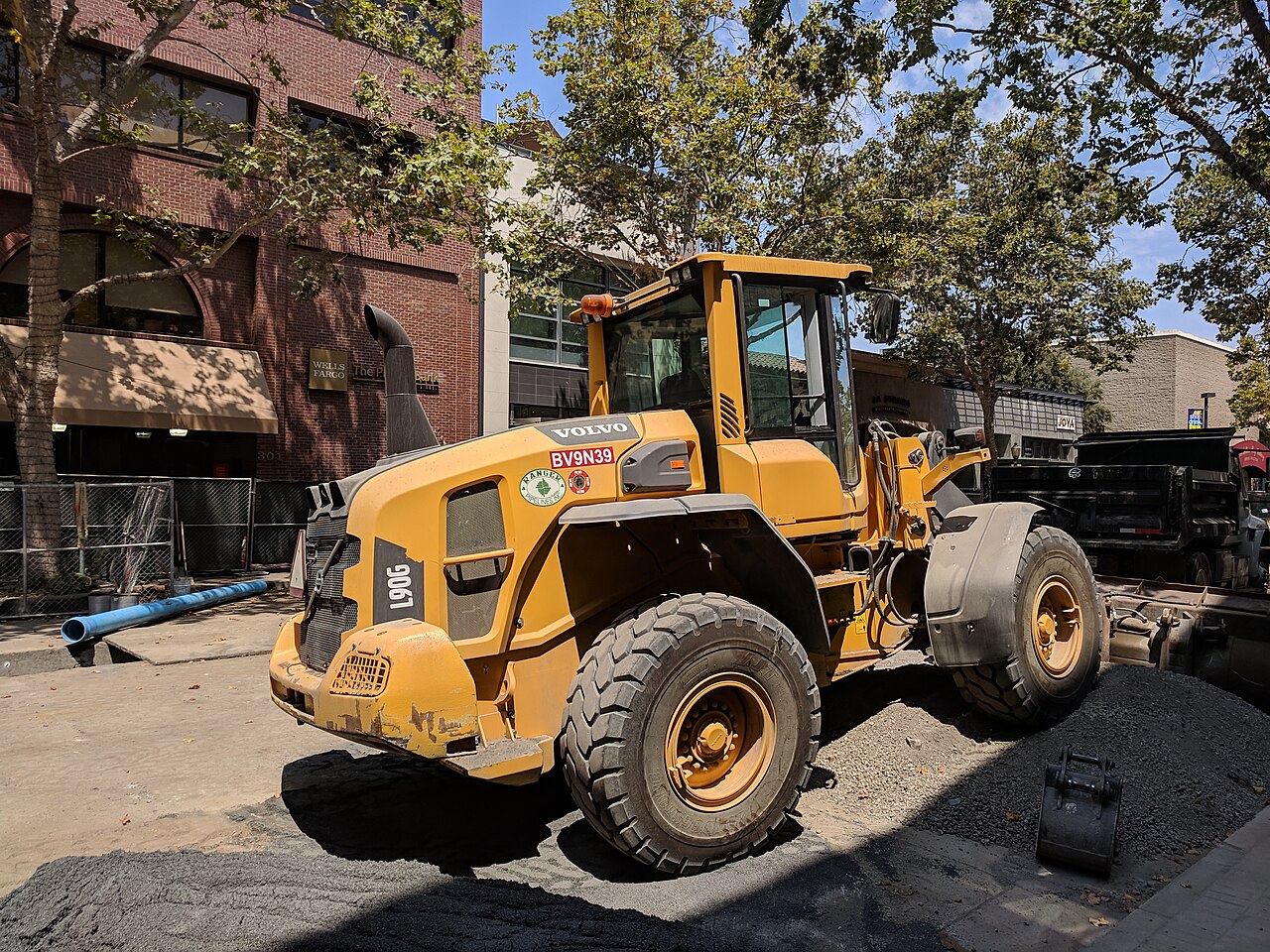 A wheel loader in service
Image: Volvo L90G loader at a job site in a Palo Alto (Grendelkhan, CC BY-SA 4.0), Wikimedia Commons. Not Komatsu's WA series discussed in the text — a representative example for reading articulated steering and the bucket linkage layout.

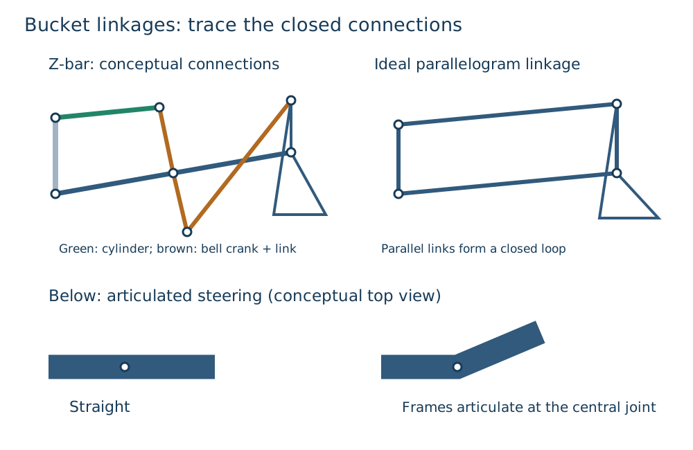
Figure 1 — The Z-bar type uses a bell crank to redirect force and gain large crowd force. The parallel-linkage type keeps the bucket angle nearly constant even through vertical motion. The lower section shows the articulation angle of articulated steering.
0. 30-Second Summary
- Most wheel loaders adopt articulated steering, in which the front and rear frames fold at the middle. Extension and retraction of the steering cylinders creates the articulation angle, changing the direction of the whole body.
- The bucket linkage comes in two types: the Z-bar (Z-link) type, which uses a bell crank to redirect the force, and the parallel-link type, which uses a four-bar parallel linkage to keep bucket angle nearly constant. The two differ in their balance of crowd force, visibility, and level-carry performance.
- Breakout force (the force generated at the bucket's cutting edge) is the amount by which the bucket cylinder's thrust is transmitted through the linkage's moment arm, and it varies with linkage angle even at the same hydraulic pressure. SAE J732 provides a shared vocabulary of loader specification terms for comparing this kind of figure.
- The hydraulic excavator handles "digging and loading" in a single machine, and the bulldozer is a machine for "pushing and leveling," whereas the wheel loader is optimized for "scooping, loading, and hauling." Differences in working radius and ground pressure also reflect this division of roles.
- Komatsu's WA series publishes engine output, bucket capacity, and breakout force from the mini class up through the medium class, providing a basis for model selection.
1. The Kinematics of Articulated Steering
Rather than steering the front wheels, many wheel loaders adopt "articulated" steering, in which the vehicle body itself folds at the midpoint between the front and rear frames. A pair of left and right steering cylinders push and pull a vertical hinge joining the front and rear frames, creating an articulation angle \gamma.
Letting a be the distance from the hinge to the front axle and b be the distance from the hinge to the rear axle, a simplified model that assumes negligible tire slip at low speed (pure rolling) gives the turning radius at the hinge position as approximately
The larger the articulation angle, the smaller the turning radius, reducing the number of back-and-forth maneuvers needed at a tight site. On the other hand, the greater the overlap between the front and rear frames, the larger the trade-off between minimum turning radius and wheelbase. Compared with front-wheel-steered vehicles, the relationship between the vehicle's center of gravity and its ground-contact point in an articulated machine changes more readily during a turn, and a sharp turn with a bucket fully loaded with earth increases the risk of tipping or rollover. This is a stability-design challenge specific to wheel loaders, distinct from the track-based turning of a hydraulic excavator or bulldozer.
2. The Bucket Linkage: Z-Bar and Parallel-Link Types
At the end of the lift arm, the bucket moves up/down, crowds (scoops in), and dumps (discharges) via a bucket cylinder and linkage (bell crank). The two representative types are as follows.
Z-bar (Z-link) type: A bell crank is placed midway along the lift arm, redirecting the bucket cylinder's motion through a "kuno-ji" (dogleg) or "Z"-shaped link to the bucket. Because a large link ratio can be used, this makes it easier to obtain a large crowd force (scooping torque) at the same cylinder thrust, suiting digging-centered work. On the other hand, at high lift-arm positions, bucket angle tends to change, somewhat complicating visibility and dump-angle control.
Parallel-link type: An auxiliary link, running parallel to the lift arm, supports the bucket, and a four-bar linkage keeps bucket angle nearly constant even as the lift-arm angle changes. This suits work such as loading a truck, where attitude stability and visibility at high positions are required. It's generally said to trail the Z-bar type in crowd force, and the two are used differently depending on application. Komatsu's own technical papers also publish research on evaluating the work-equipment performance of parallel-link machines.
In either type, the bucket cylinder's thrust F_{cyl}=\Delta p\,A_{cyl} is converted, via the linkage, into torque about the bucket's rotation axis. Because the moment arm r_m(\phi) changes with linkage angle \phi, the breakout force generated at the bucket tip depends on both cylinder thrust and linkage geometry:
where r_{edge} is the distance from the bucket's rotation center to the cutting edge. A catalog's "maximum breakout force" is typically a value measured near the bucket attitude that maximizes this ratio, and the same force isn't produced across every attitude in actual work.
3. Breakout Force and How to Read the Specs
Breakout force is defined as the force generated at the cutting edge when a load is applied, from the bucket dug into the ground, up to the cylinder's relief pressure. SAE J732 is a standard that uniformly defines loader specification terminology, providing a shared framework for comparing figures such as breakout force and bucket capacity across makers. However, because the meaning of a figure changes with the measurement conditions (bucket attitude, lift-arm angle, and which cylinder is the primary one), it's necessary to confirm whether catalog values were measured under the same test conditions before comparing them.
In Komatsu's public specs, the WA40-8's maximum bucket breakout force is stated as 29.4–29.9 kN (3000–3050 kgf). Even within the same series, breakout force increases with machine size, through the combination of cylinder bore, hydraulic pressure, and link ratio.
4. Division of Roles With the Hydraulic Excavator and Bulldozer
The hydraulic excavator and bulldozer covered elsewhere on this site are both primarily aimed at "cutting and leveling the ground." The wheel loader is optimized differently — for "scooping up earth, crushed stone, or aggregate that already exists, and loading it onto a haul vehicle or stockpile."
| Aspect | Hydraulic excavator | Bulldozer | Wheel loader |
|---|---|---|---|
| Main action | Digging, loading, grading | Pushing earth, leveling | Scooping, loading, hauling |
| Travel method | Tracks (can pivot/counter-rotate turn) | Tracks | Tires, articulated steering |
| Ground pressure | Low (tracks) | Low (tracks, suited to heavy loads) | Higher (tires, premised on road travel) |
| Travel speed | Slow | Slow | Relatively fast (moving between sites/within a site) |
| Best suited to | Natural ground, slopes, trenching | Bulk earthmoving, leveling | Loading piled earth, crushed stone, snow, etc. |
The wheel loader chooses tires because it often self-propels on public roads or graded ground within the site, is faster than tracks, and its wearing parts are easier to replace. On the other hand, it's inferior to tracked machines in traction on soft or rough ground, and in the tight maneuverability of a counter-rotating turn. On site, a common division of labor is seen in which a hydraulic excavator digs and piles earth, and a wheel loader loads it onto a dump truck.
5. The Range of Wheel Loaders Seen in Current Products
| Model | Engine rated output (net) | Bucket capacity | Max breakout force (bucket) |
|---|---|---|---|
| Komatsu WA40-8 (mini wheel loader) | 28.4 kW (38.6 PS) | 0.5–0.6 m³ | 29.4–29.9 kN (3000–3050 kgf) |
| Komatsu WA80 | 44.3 kW (60.2 PS) | 0.9 m³ | See official spec sheet |
| Komatsu WA100-8 | 73.1 kW (99.4 PS) | 1.3 m³ | See official spec sheet |
Output and bucket capacity are roughly proportional, but because breakout force is also affected by link ratio and cylinder bore, the trend differs by maker and model even within the same output class. Model selection needs to weigh not just output and bucket capacity, but also the linkage type (Z-bar or parallel-link) against the required loading height and visibility on site.
6. Summary
A wheel loader's performance can't be measured by engine output and bucket capacity alone. The geometry of articulated steering, which folds the body for tight maneuverability, and the ratio by which the linkage converts cylinder thrust into force at the cutting edge, are what determine actual workability. The choice between Z-bar and parallel-link type is a trade-off between digging force and attitude stability/visibility at height, and selecting a model with an understanding of the division of roles with the hydraulic excavator and bulldozer is what determines overall site productivity.
Are loaders and excavators suited to identical work?
A loader combines travel with its bucket; an excavator digs with its arm. Compare digging position, travel distance, footing, and cycle time.
References
- Komatsu Customer Support — WA100-8 Product Information
- Komatsu Customer Support — WA30-6E0 Product Information
- Komatsu — WA40-8 Mini Wheel Loader Specifications
- Komatsu Technical Report — Applying DSS to Work-Equipment Performance of Parallel-Link Wheel Loaders
- SAE International — J732: Specification Definitions - Loaders
Current step · 3 / 7 · Construction Machinery Engineering
Comments
Please log in to post a comment
No comments yet.