Contents — find the section you need
Background and reading guide
Background Basic force, motion and energy terminology; use the linked background explanations.
Fundamentals · Explanations of principles, structure and trade-offs.
Seen from a distance, a hydraulic excavator looks like a "giant scoop" — a cab and long arm perched on top of a pair of tracks. In reality it is a sensor-equipped mobile manipulator: it converts the engine's mechanical energy into high-pressure fluid via a hydraulic pump, then uses multiple proportional valves to drive the boom, arm, bucket, swing, and travel simultaneously. Raising digging precision requires handling not just cylinder extension, but also the machine's tilt, swing angle, the flex in each link, and the reaction force from the ground.
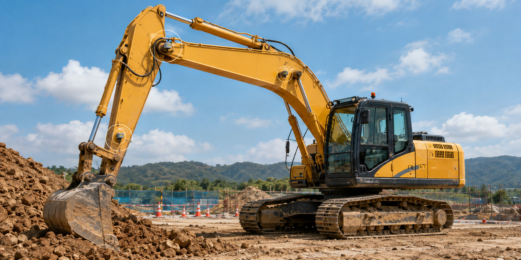
Photo 1 — An educational concept illustration for reading excavator structure. The white circles are explanatory candidate sensor locations, not a claim about a standard feature or a particular model.
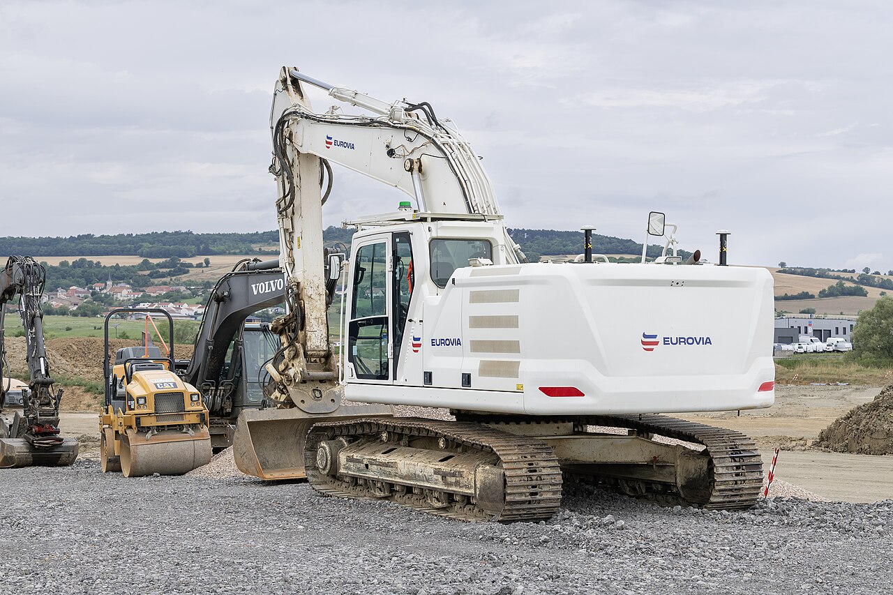 A hydraulic excavator in service
Image: CAT 326 (Alexandre Prevot, CC BY-SA 4.0), Wikimedia Commons. Not the specific ICT-equipped Komatsu or Caterpillar models discussed in the text — a real-machine example for reading the boom, arm, and bucket layout.

0. 30-Second Summary
- The power flow runs "diesel engine → hydraulic pump → control valve → cylinder/hydraulic motor → linkage/tracks." Hydraulics can deliver large forces smoothly at low speed.
- If the boom, arm, and bucket angles are q_1,q_2,q_3 and the link lengths are l_1,l_2,l_3, the bucket tip can be found via forward kinematics. Combining IMU data, cylinder stroke, and swing angle lets you estimate the 3D position of the cutting edge.
- Planetary gears are used in the undercarriage's final drive and the upper structure's slew reduction gear. They deliver large torque from a small input, but tooth-surface loading, lubrication, heat, and backlash determine service life.
- Komatsu's ICT-equipped machines and Caterpillar's Cat Grade/Payload use GNSS, IMU, hydraulic sensors, and 3D design data to help operators avoid "digging too deep" or "loading too much." Specs vary by model, region, and options, so you need the reference date on official materials.
- Autonomous-excavation research combines attitude estimation from multiple IMUs, ground-surface recognition via camera/LiDAR, model predictive control, and reinforcement learning. Changing soil conditions and safety monitoring remain the walls standing between this and practical deployment.
1. First, Split the Machine into Four Parts
Break down the hydraulic excavator's structure so that the flow of force is never interrupted.
- Undercarriage: The left and right tracks, travel hydraulic motors, reduction gears (final drives), idlers, sprockets, and rollers transmit force to the ground.
- Upper structure: Carries the engine, pump, tank, cab, and counterweight, and rotates relative to the undercarriage via the swing bearing and swing reduction gear.
- Work equipment: The boom, arm (stick), and bucket, driven by hydraulic cylinders. Wear at each pin and the stiffness of the links directly affect cutting-edge accuracy.
- Control and sensing: Joysticks, electromagnetic proportional valves, pressure/temperature/flow sensors, IMU, GNSS, cameras, and communication terminals are what make the machine "measurable."
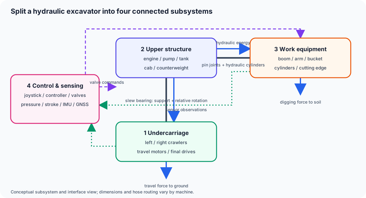
Figure 1 — The four parts are not isolated boxes. The undercarriage supports the upper structure through the slew bearing; the upper pump distributes hydraulic energy to the work equipment and travel motors; control and sensing issue valve commands and return observations.
The name "excavator" makes the bucket look like the sole protagonist, but the actual digging force is determined by the combination of pressure and posture across the boom, arm, and bucket cylinders. Even at the same hydraulic pressure, the torque transmitted to the ground changes with link angle, so catalog digging-force figures should never be compared without the working posture attached.
2. Hydraulics Basics: Pressure Is Force, Flow Is Speed
Let the hydraulic cylinder's piston area be A and the pressure differential be \Delta p. The ideal thrust is
If the pump supplies flow rate Q, piston speed is
Raising pressure gives more force; increasing flow gives faster motion — but pump shaft power
rises at the same time. Since engine output has no slack to spare, running multiple operations simultaneously requires coordination among pump discharge-flow allocation, load sensing, pressure-compensating valves, and engine speed control.
The classic on-site headaches in a hydraulic circuit are cavitation and heat. If the pressure on the suction side, drawing from tank into the pump, drops too low, bubbles form; when they collapse, they damage metal surfaces. At leaks, restrictions, and valve orifices, pressure energy converts to heat, which is why coolers and hydraulic-fluid viscosity management are necessary. Even with electrification, as long as hydraulic actuators remain, this thermal design problem never goes away.
3. Kinematics of the Boom, Arm, and Bucket
In a simplified planar model, place the upper structure's pin at the origin, let the boom/arm/bucket link lengths be l_1,l_2,l_3, and the angles q_1,q_2,q_3. The bucket tip position is
Adding the swing angle q_0 gives horizontal-plane coordinates
This is forward kinematics.
On older machines that cannot measure the angle directly, the angle is back-calculated from cylinder length s. If the distance between two pins forms a triangle, the law of cosines
recovers the joint angle. But ignore pin play, link deflection, and 3D misalignment of the cylinder mounting points, and you get several centimeters of error at the tip. Elastic deformation when pressing against soil pulls the machine away from a model calibrated under no load.
4. Why Mount IMUs on the Boom and Arm
An IMU measures each link's attitude changes at high frequency using an accelerometer and gyroscope. Placing IMUs at four locations — upper structure, boom, arm, and bucket — lets you estimate each link's absolute attitude and subtract adjacent links' relative angles. Because a standalone IMU accumulates bias through integration, it's combined with static calibration at startup, gravity direction, cylinder length, swing angle, and GNSS/total station (TS).
A field study on excavators for forestry access roads mounted IMUs at four locations — upper structure, boom, arm, and bucket — and reported an average cutting-edge height error of 1.03 cm, while the 3D error reached as much as 7.05 cm due to heading error. This doesn't mean "more IMUs always means higher accuracy" — it tells us that magnetic heading disturbance, mounting stiffness, initial attitude, and ground-truth measurement on the soil side matter just as much.
The estimation loop used in research and implementation looks like this:
- Read the IMUs at roughly 200 Hz and integrate each link's attitude as a quaternion.
- Interpolate cylinder stroke, swing encoder, and pressure to the same timestamps.
- Fuse the forward-kinematics predicted angles with the IMU relative angles via EKF/factor graph.
- Correct drift using external observations such as GNSS, laser trackers, or stereo cameras.
- Log the distance between the cutting edge and the design surface, along with pressure, flow, and fuel consumption.
5. Planetary Gears in the Swing Body and Final Drive
Hydraulic motors spin at high speed and moderate torque, which is too fast to drive the tracks or swing bearing directly. That's where planetary reduction gears come in. Combining four elements — the sun gear, multiple planet gears, the ring gear, and the carrier — yields a large reduction ratio while staying coaxial.
For a simple planetary gear train, with tooth counts Z_s,Z_r and angular velocities \omega_s,\omega_r,\omega_c, the speed relation is
Fixing the ring, feeding input through the sun, and taking output from the carrier slows output rotation while increasing torque. Because multiple planets share the load, this achieves higher torque density than a spur-gear train of the same outer diameter.
In the swing reduction gear, tooth-surface impact and backlash become a problem as the upper structure's inertia is accelerated and decelerated. In the final drive, service life is governed by the impact torque of a track climbing over a rock, sealing against mud and water, and long stretches of low-speed, high-torque operation. Rather than comparing planetary tooth counts alone, you need to look at the hydraulic motor's displacement, relief pressure, reduction ratio, lubrication, bearings, and track pitch as a single drivetrain.
6. Current ICT Construction and Product Examples
Komatsu's ICT-equipped construction systems combine a GNSS antenna, an inertial measurement unit (IMU), boom/arm/bucket angle-and-stroke detection, and 3D design data to display the difference between the cutting-edge position and the target surface on the cab monitor. Komatsu's official ICT construction-machinery materials describe the system configuration, including the sensor unit, and its use in machine guidance/machine control on hydraulic excavators. In the field, adoption often starts not with "automatic digging" but with guidance that keeps the machine from exceeding the design surface, as-built recording, and reducing the number of survey passes.
Caterpillar's Next Generation 320 is one example of a product family that combines hydraulic control, engine speed, fuel efficiency, Cat Grade, Cat Payload, and VisionLink telematics. The manufacturer's own published figures estimate fuel and CO₂ reductions versus the prior generation, using machine operating data and fuel type. Caterpillar has also shown development machines aimed at electrification, including the 301.9 battery-electric mini excavator and the 320 battery-electric medium excavator. This doesn't mean "everything goes battery tomorrow" — it means the range of use-case-specific options is expanding, factoring in charging time, on-site power availability, utilization rate, and hydraulic-system efficiency.
When comparing products, it helps to line up the following items on the same basis.
| Perspective | Values to check | Easy to overlook |
|---|---|---|
| Digging force | Rated force at bucket/arm/boom | Varies with posture, standard, and hydraulic pressure |
| Working range | Max digging depth, reach, dump height | Combination of bucket, arm length, and track width |
| Hydraulics | Pump type, max flow, relief pressure | Flow allocation during simultaneous operation |
| Control | Grade, Payload, GNSS/IMU, remote monitoring | Options, region, communication environment |
| Environmental performance | Fuel economy, emissions regulation, motor rating | Utilization rate, charging infrastructure, cold-weather performance |
| Maintenance | Filter intervals, oil analysis, remote diagnostics | Parts supply and service network |
7. Autonomous Excavation Research: Treating the Ground as an "Unknown Load"
Autonomous excavation is harder than a robot arm following a known trajectory. As the bucket enters the soil, digging resistance, moisture content, gravel, and collapse all shift simultaneously, so the required pressure changes even at the same joint angle. Research estimates joint torque and attitude from hydraulic pressure and IMU data, recognizes ground shape with camera/LiDAR, and updates the excavation trajectory using model predictive control (MPC) or reinforcement learning.
A 2022 study estimated a construction machine's full-body pose from multiple IMUs and a kinematic model, reporting an average joint-angle RMSE of 1.71 degrees, along with optimization of sensor placement and count. In 2025, a study was published that added inter-link motion information to IMU-derived joint angles and validated hydraulic-excavator cutting-edge position estimation on real hardware. These aren't identical to standard features in current products, but they concretize the sensor placement and error budget that future machine-control systems will need.
Breaking autonomy into stages, a realistic order looks like this:
- Machine guidance that displays cutting-edge position
- Machine control that limits valve commands to keep from exceeding the target surface
- Work assistance that automatically logs payload, fuel, and cycle time
- Supervised autonomous excavation including ground recognition and trajectory generation
- Site-wide autonomous construction coordinating with other machines, workers, and dump trucks
8. Conclusion: Viewing Hydraulics, Gears, and Estimation Under One Error Budget
A hydraulic excavator's performance isn't determined by engine output or bucket capacity alone. Hydraulic pressure and flow, link geometry, IMU bias, cylinder play, planetary-gear backlash, ground resistance, and communication latency all stack up into cutting-edge position and work time.
When examining a machine, writing down first "which part, measured by which sensor, converted into which coordinate frame, controlled to what uncertainty in centimeters" lets you compare catalog figures and research papers on the same footing. Treating electrification and AI autonomy as technologies layered on top of the existing mechanical system — hydraulics, reduction gears, and safety monitoring included — makes it easier to avoid getting swept up by news headlines.
Do pressure and flow do the same job?
For fixed piston area, pressure determines force and flow determines speed in the ideal model. More force and faster motion are different requirements.
References
- Komatsu ICT Construction Machinery Materials
- Caterpillar — Excavator Evolution
- Caterpillar — Battery Electric Machines
- Forestry and Forest Products Research Institute — Attitude Estimation Accuracy of Hydraulic Excavators
- IMU-based full-body pose estimation for construction machines
- Hydraulic excavator cutting-edge position estimation using inter-link motion information
- A comparative study on cutting-edge position recognition for hydraulic excavators
Current step · 1 / 7 · Construction Machinery Engineering
Comments
Please log in to post a comment
No comments yet.