Contents — find the section you need
Background and reading guide
Background Basic force, motion and energy terminology; use the linked background explanations.
Fundamentals · Explanations of principles, structure and trade-offs.
RTK-GNSS is the technology that lets you know "where you are in the field, to within a centimeter." But on its own, it doesn't keep you on the row, and it doesn't change how much fertilizer goes down. Only when position information is converted into a guidance line, deviation from that guidance line is fed back into a steering angle, and the whole chain is connected to position-linked prescription maps does "RTK guidance" actually function as labor-saving, precision farm work. This article traces that chain of conversions from the standpoint of agricultural machinery engineering.
The principles of positioning itself — base and rover stations, carrier-phase correction, dual-frequency measurement that removes ionospheric delay, and so on — are covered in detail in this site's How GNSS Works, and the Major Products. This article assumes that background and focuses narrowly on how agricultural machinery converts RTK positioning into guidance, steering, and variable-rate work. Unless otherwise noted, product specs and features are based on each maker's public information confirmed as of September 4, 2026.
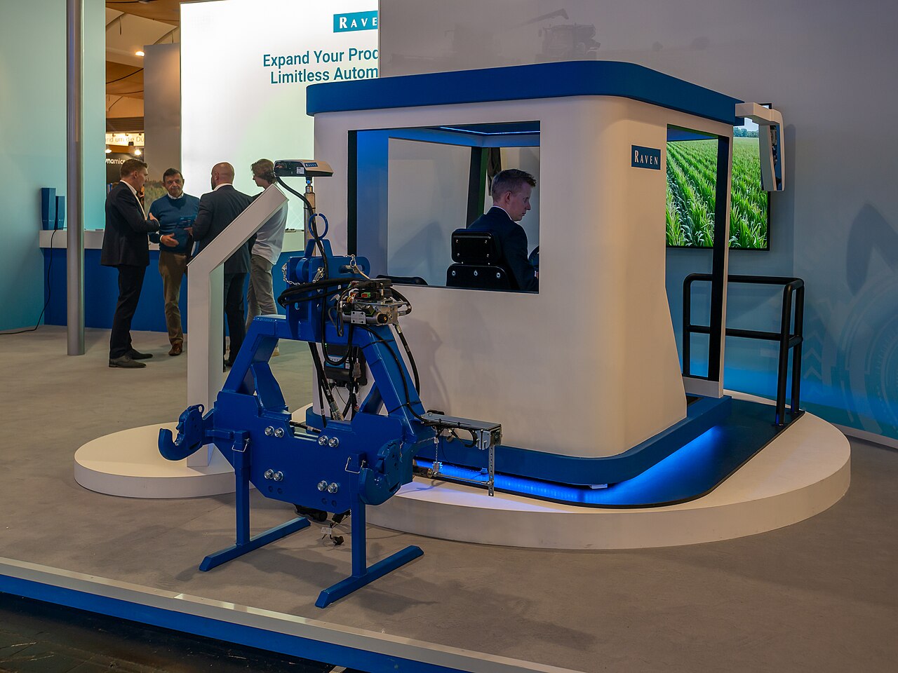 A GNSS guidance kit on display
Image: Raven CRx+ Guidance Kit, Agritechnica 2023, Hanover (MB-one, CC BY-SA 4.0), Wikimedia Commons. This is a trade-show demonstrator, not a photo of the kit mounted on a working tractor — a representative example of the receiver and hitch-control hardware behind autonomous steering discussed in the text.
.jpg)
30-Second Summary
- RTK-GNSS uses carrier-phase correction from a base station or a correction network to shrink the several-meter error of standalone positioning down to centimeter class. The value on the agricultural-machinery side hinges on how this position accuracy is converted into guidance lines, steering, and application rate.
- Guidance comes in stages. "Visual guidance," where a person steers while watching a line on a screen; "autonomous steering," where GNSS plus hydraulics/motors hold a straight line; "turn automation," which also coordinates headland turns; and "supervised robotic farm machinery," which runs under human supervision — conflating these stages leads to confusion about both the benefits of adoption and the safety measures required.
- Guidance lines include AB lines (straight-line reference), curve lines, contour lines (ridges that follow elevation contours), and perimeter lines (following the field boundary), chosen according to field shape and implement width.
- Control doesn't rest on GNSS alone. An IMU supplies attitude, wheel-speed and steering-angle sensors supply machine state, and feedback control that returns lateral and heading deviation to a steering angle forms the foundation.
- Differences in correction method (D-GNSS vs. RTK, fixed base station vs. network-type VRS, radio vs. NTRIP vs. PPP-RTK) affect not just accuracy but also coverage area, convergence time, and dependence on communication infrastructure.
- The positional repeatability RTK provides only becomes material for farm-management decisions once it's combined with variable-rate fertilization, variable-rate seeding, and yield maps. Accurate position doesn't guarantee the prescription itself is correct.
1. Distinguishing the Four Stages of Guidance
The phrase "self-driving tractor" actually lumps together four stages that differ substantially.
| Stage | What it does | The human's role | Common names |
|---|---|---|---|
| Visual guidance | Displays the guidance line and deviation on a monitor | Person operates the steering wheel | Light bar, Track-Guide, etc. |
| Autonomous steering | Holds a straight line via steering motor/hydraulics based on GNSS position | Person is on board, handles turning, implement operation, and monitoring | Auto-steer, straight-line assist |
| Turn/work-coordination automation | Coordinates headland turns, implement raising/lowering, and speed changes | Person is on board, mainly monitoring and intervening | Automatic turning, headland management |
| Supervised robotic farm machinery | The above, plus driving unmanned or with minimal intervention | Person supervises around the field, bears responsibility for emergency stop | Robot tractor, Agri Robo series |
Conflating these stages leads to the misunderstanding that "we installed auto-steer, so it can be used unmanned," or conversely to the misjudgment that "it's just visual guidance, so no safety checks are needed." Before adoption, it's worth clarifying which stage your own operation actually requires.
2. Designing the Guidance Line: AB Lines, Curve Lines, Contours
Figure: Created by Duskcoil. Actual guidance lines are used in combination depending on field shape, implement width, and slope.
An AB line generates a family of guidance lines shifted parallel to each other by the working width, based on a straight line connecting two points, A and B, within the field. It's the easiest to work with for near-rectangular fields or dryland farming with straight ridges. A curve line records the first pass as a curve and then shifts that shape in parallel for subsequent passes; it's used for paddies and irregular fields that trace an arc along a levee or waterway. A contour keeps a path close to the elevation contour, and is sometimes used to suppress soil erosion and drainage imbalance on sloped land.
Whichever guidance line is chosen, effectiveness depends on how well it fits the field's shape and the implement's width. In extremely irregular fields, switching guidance lines or re-setting them per sub-block becomes necessary, demanding operational design beyond simply "being able to drive straight."
3. The Control Loop: From Position to Steering Angle
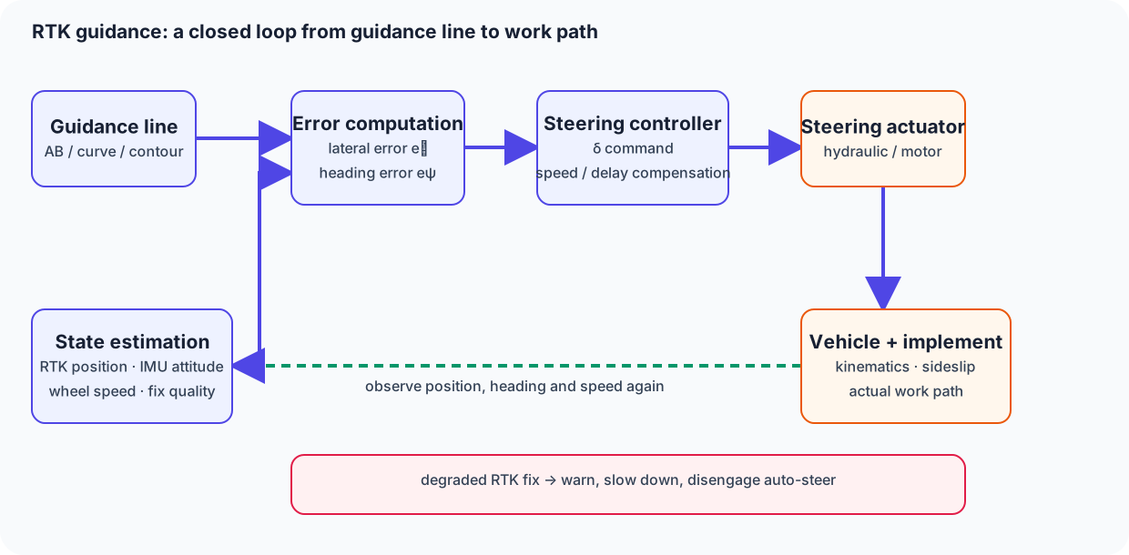
Figure: Created by Duskcoil. Actual controllers include terms that compensate for vehicle speed, delay, and side-slip.
As also touched on in the article on rice transplanters, which covers straight-line tracking, if we let the lateral deviation from the guidance line be e_y, the difference between the vehicle heading and the guidance line's heading be e_\psi, and the steering angle be \delta, a simple proportional controller can be written as
What matters here is that what the GNSS antenna reports is a single point on the vehicle body — not the tip of the implement or the planting unit. Roll on a slope, tire side-slip, and hitch play all shift the antenna's trajectory away from the actual working line. That's why RTK guidance doesn't rely on GNSS alone: an IMU supplies roll, pitch, and yaw, wheel speed or motor rotation supplies short-term motion, and the fused estimate from these is what gets passed to the controller.
When correction data is temporarily interrupted (a downgrade from FIX status to FLOAT or standalone positioning), position accuracy degrades abruptly. If the controller fails to detect this and keeps operating with gains tuned for high precision, it can cause weaving or abrupt corrective motion. A safe implementation continuously monitors correction-quality status and, when it degrades, transitions to a warning, deceleration, or disengagement of auto-steer.
4. Where Differences in Correction Method Matter in Practice
| Correction method | Approximate accuracy | How coverage area works | Practical caveats |
|---|---|---|---|
| GNSS alone / D-GNSS | Several meters to tens of cm | No constraint | Often insufficient for auto-steer that must not stray off the row |
| RTK (fixed base station) | cm-class | Roughly within tens of km of the base station | Requires base station installation/maintenance and radio line-of-sight |
| RTK (network-type / VRS) | cm-class | Within communication infrastructure coverage | Depends on cellular signal quality and NTRIP delivery latency/dropouts |
| PPP-RTK (correction delivery service) | cm-class | No base station needed; usable over wide areas and overseas | Convergence time can take tens of seconds to several minutes |
Kubota's REXIA GS specification (80–105 hp) comes with a standard RTK-GNSS antenna and is described as enabling straight-line work with an error of roughly ±2–3 cm against the reference line. The same release says that a separate RTK correction-information service and communications terminal are required, so this product material alone cannot establish how a nationwide base-station network is operated. Kubota: Expanding the lineup of products equipped with auto-steer John Deere, on the other hand, publishes a tiered accuracy structure for AutoTrac: an error of about 33 cm with 95% probability under SF1 correction, and about 10 cm with 95% probability using a ground-based RTK base station configuration — a design philosophy that separates use cases by correction grade. John Deere AutoTrac product information The question isn't which strategy is superior, but which fits your own distribution of fields, communication environment, and payback period — the base-station type or the network-delivery type.
5. NTRIP and Radio: How Correction Data Reaches the Machine
The path that delivers RTK correction data to a rover splits mainly into a dedicated radio modem (a UHF/VHF radio link from the base station) and a route that connects, via cellular network, to an NTRIP (Networked Transport of RTCM via Internet Protocol) delivery server on the internet. The radio approach doesn't incur communication costs but is subject to line-of-sight distance and output-power restrictions, while the NTRIP approach carries the risk of correction dropouts when out of coverage or when the line is congested. Trimble's GFX series is configured so RTK, VRS, and Trimble RTX (PPP-RTK) can be chosen depending on conditions, and its roadmap also includes support for Michibiki's CLAS. Trimble: Renewed farm auto-steer system GFX series The very fact that multiple correction paths are provided reflects a design intent: don't let a single communication failure halt work.
6. Connecting to Variable-Rate Fertilization and Variable-Rate Seeding
The real value of RTK guidance isn't just driving straight. Given a prescription map q(x,y) built from position-linked yield maps, soil sensor data, and past application history, the machine can track its fertilization or seeding rate to the target application amount at each position while running along the guidance line.
That's the ideal, simple form — but in practice, if the response lag of the fertilizer/seeder unit, the time needed to switch application rate, and the offset between position and the actual drop point aren't accounted for, over- or under-application occurs at block boundaries. Iseki's Smart Top-Dressing System illustrates the concept: a laser optical sensor measures crop growth in real time and works with GNSS auto-steer and a variable-rate fertilizer applicator to perform variable top-dressing that's less affected by environmental conditions. Iseki: Smart Top-Dressing System The mechanisms of the seeder and fertilizer applicator themselves are covered in detail in the article on seeders and fertilizer applicators.
7. Reading Current Product Examples
| Maker / product example | Key points readable from public information | Engineering perspective | Official information |
|---|---|---|---|
| Kubota REXIA GS spec / KSAS GS Link | RTK-GNSS standard equipment, error ±2–3 cm, reference line auto-registered to KSAS | A design that integrates a proprietary base-station network with a work-record cloud | New product lineup |
| John Deere AutoTrac | Publishes accuracy tiers by correction grade: SF1 / SF2 / RTK | Lets you select correction grade separately from use case (tolerance for straight-line coarseness) | AutoTrac |
| Trimble GFX series / NAV-960 | Supports RTK, VRS, and RTX; enhanced CPU improves convergence and tracking accuracy to the AB line | Ensures resilience against communication failure by holding multiple correction paths | GFX series |
| Yanmar SMARTPILOT / retrofit GNSS guidance | Offers guidance display and auto-steer as distinct products, and flags accuracy degradation from satellite conditions | Separates "just displaying" from "actually steering" as distinct products | SMARTPILOT |
What matters in a product comparison isn't just the top-line accuracy figure. It should be evaluated together with whether there's a base station, communication costs, convergence time, compatibility with existing implements, and fallback behavior on failure — the whole picture of fit with your own operation.
8. Safety Design to Settle Before Adoption
RTK guidance's safety isn't determined by "whether position is accurate" alone. Geofencing to prevent crossing field boundaries, how auto-steer is disengaged when correction drops out, behavior during turns and implement raising/lowering, attention to people, vehicles, waterways, and power lines, and the means and person responsible for emergency stop — all of this needs to be documented as operating rules before adoption. Especially at the supervised-robotic-farm-machinery stage, automation shouldn't proceed while leaving vague what the supervisor checks, and at what timing.
Summary
RTK guidance is a multi-stage conversion system: it converts a centimeter-class absolute-position input into guidance lines — AB lines, curve lines, contours — converts those into a steering angle via feedback control on lateral and heading deviation, and further converts that, combined with a prescription map, into application rate. Rather than comparing positioning-accuracy figures alone, evaluating the guidance-line design, the redundancy of the correction path, the connection to variable-rate work, and the safety design for communication dropouts is what translates into real farm-management value.
Does accurate RTK eliminate implement error?
The antenna and working point differ. Mounting offsets, vehicle tilt, and implement sway contribute to working-point error.
References
- Duskcoil: How GNSS Works, and the Major Products
- Duskcoil: Agricultural Machinery Engineering 101: The Rice Transplanter
- Kubota: Expanding the lineup of products equipped with auto-steer (confirmed September 4, 2026)
- Kubota: The basics of auto-steer (confirmed September 4, 2026)
- John Deere: AutoTrac (confirmed September 4, 2026)
- Trimble: Renewed farm auto-steer system GFX series (confirmed September 4, 2026)
- Yanmar: SMARTPILOT (confirmed September 4, 2026)
- Yanmar: GNSS Guidance & Auto-Steer (confirmed September 4, 2026)
- Iseki: Smart Top-Dressing System (confirmed September 4, 2026)
Current step · 2 / 7 · Agricultural Machinery Engineering
Comments
Please log in to post a comment
No comments yet.