Contents — find the section you need
Background and reading guide
Background Basic force, motion and energy terminology; use the linked background explanations.
Fundamentals · Explanations of principles, structure and trade-offs.
A tractor isn't "a vehicle that tills a field." It's a mobile power and control platform that allocates engine output, in the required proportion, among the traction force that pushes the ground to move forward, the PTO that spins rotary implements, and the hydraulic three-point linkage that lifts an implement and shapes its attitude. A rotary tiller, plow, seeder, fertilizer spreader, mower, or baler each demands a different resistance, rotation speed, height, and travel speed. Tractor design is the engineering of receiving all of these on one machine, without over-compacting the soil, and working in a straight line at a consistent depth.
This article focuses on wheeled tractors for paddy and dryland fields, while also covering tracked types. Unless otherwise noted, product specs and features are based on each maker's public information confirmed as of September 3, 2026. Always give priority to the owner's manual for each model's allowable loads, PTO speed, hydraulic outlets, road travel, and safe operation.
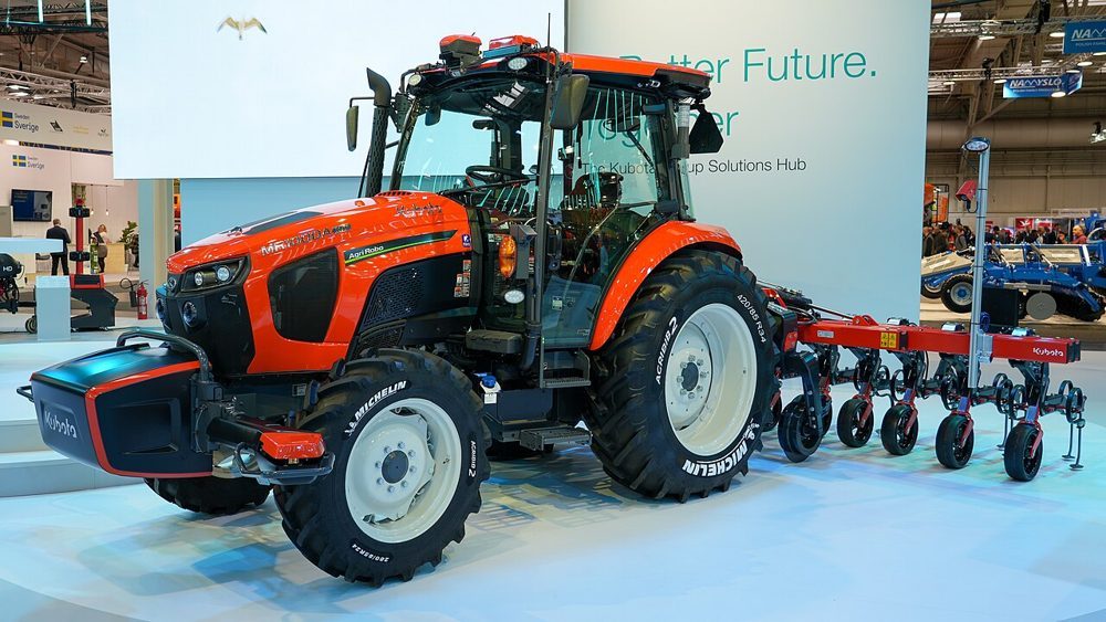 Kubota AgriRobo MR1000A
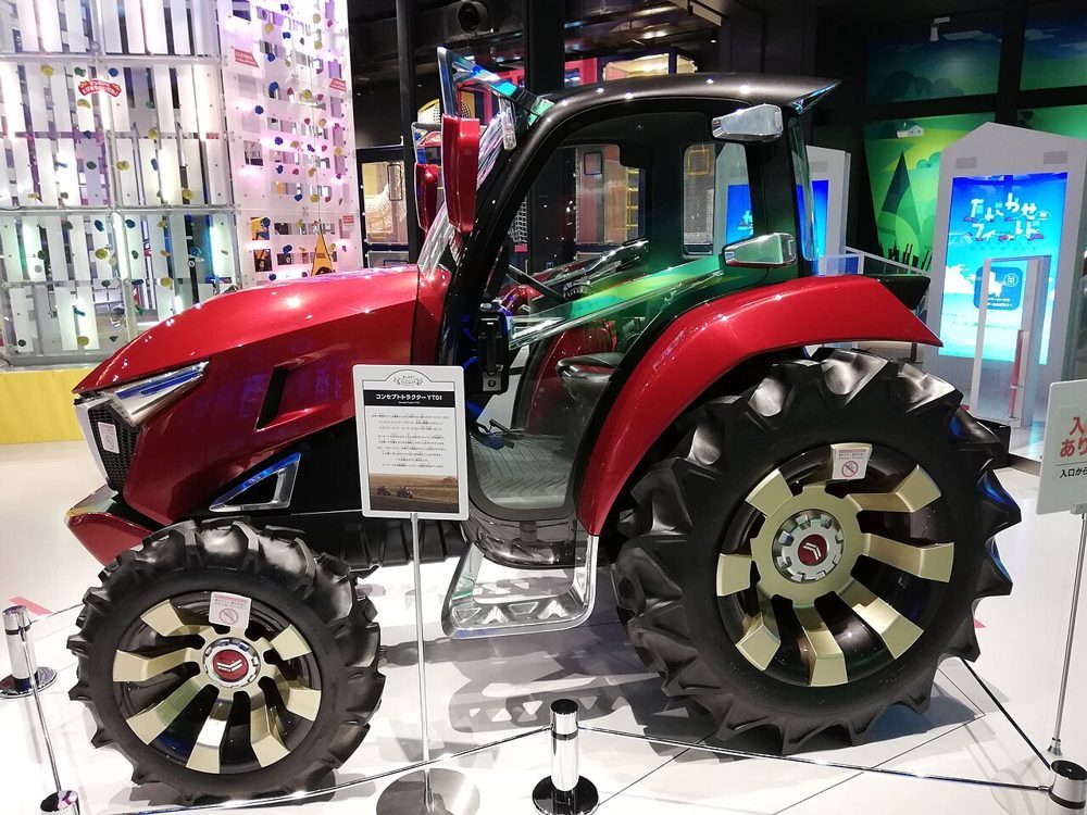 Yanmar YT01 concept
Images: Kubota AgriRobo MR1000A (MarcelX42, CC BY-SA 4.0) / Yanmar YT01 (CC0), Wikimedia Commons. YT01 is a design-study show vehicle, not a production specification.
.jpg)
.jpg)
30-Second Summary
- A tractor's output becomes traction force at the tire or crawler contact patch, rotational power to implements via the PTO, and implement height/attitude via hydraulics and the three-point linkage. Work capacity isn't determined by horsepower alone.
- Traction is determined by friction/shear with the soil, vehicle weight, load transfer, and slip. Too little slip means insufficient weight; too much wastes fuel churning up soil and damages it. Appropriate ballast and tire pressure matter.
- The PTO is a standardized rotational output shaft, generally transmitting 540 or 1,000 rpm to implements. Getting rotation speed, guards, or inertial load wrong is dangerous, and the implement's requirements must be checked.
- The three-point linkage is a mechanism that supports an implement with one upper point and two lower points. Draft control feeds back tillage depth from towing resistance, while position control holds a set height. Blending the two makes it easier to keep the finished result stable even amid undulation or soil-quality variation.
- Diesel remains dominant because of fuel's energy density for sustained, high-load operation, ease of refueling, high torque at low RPM, and compatibility with existing hydraulic/PTO systems. Electrification is advancing first in small machines, auxiliary equipment, and hybrids; for large machines towing all day, battery weight and charging remain challenges.
- Linking RTK-GNSS, IMU, wheel speed, cameras, and yield/soil sensors enables a progression from straight-line assist to autonomous steering, variable-rate fertilization, and closed-loop control of tillage depth and travel speed. But positioning quality, implement lateral offset, and obstacle monitoring must be handled separately.
1. History: From Steam to a "Power Source You Can Choose Implements For"
Mechanized farming didn't start out looking like today's tractor. 19th-century steam traction engines could deliver high output, but were heavy, hard to start and water, and prone to sinking in wet fields. As internal combustion engines spread, lightweight gasoline/kerosene tractors developed that carried their own fuel into the field and towed a plow directly. In the first half of the 20th century, pneumatic tires, diesel engines, hydraulic lift, and the three-point linkage came together, establishing today's basic form: swap out a variety of implements without swapping the machine itself.
The critical turning point was the tractor becoming, not merely a towing vehicle, but a standardized-interface base for farm work. The PTO hands off rotational power, the three-point linkage hands off support and lift, hydraulic outlets hand off cylinder or motor force, and electrical connectors and communication such as ISOBUS hand off control information. Implement makers can design to these interfaces instead of building a dedicated power vehicle for every model. Today's precision agriculture also rides on top of this idea of separating the machine from the implement.
Japan has a wide range of conditions — small-plot paddies, wet paddies, dryland farming, orchards — where small- and large-horsepower machines, wheeled, half-track, and full-track types have all coexisted. In rice cultivation, puddling/tilling combined with a rotary tiller is representative; in dryland farming, high-draft-resistance work such as plowing, subsoiling, and seeding is representative. Beyond simply scaling up the machine, the work system — including field plot layout, headlands, farm roads, drainage, and soil layers — needs to be designed.
2. Thinking About Three Outputs at Once
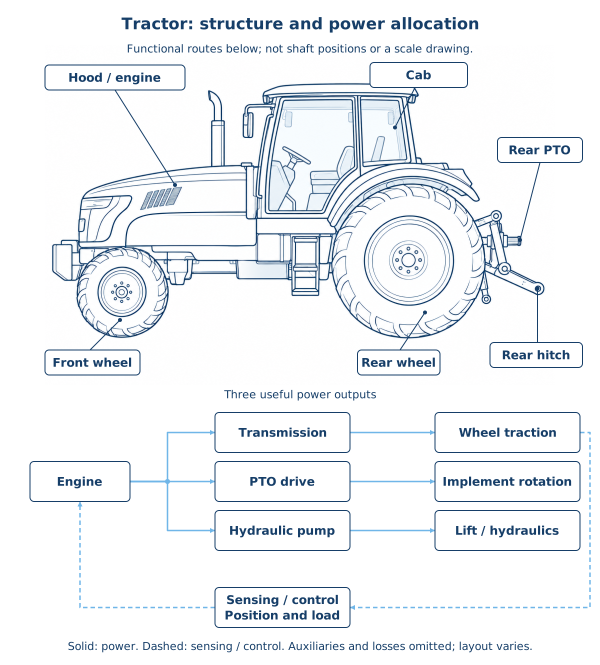
Figure: Duskcoil. AI-generated tractor line art with labels and functional routes generated from a shared specification; not a machine drawing.
Letting engine output be P_e, conceptually it can be split as
P_{travel} is travel, P_{pto} is the PTO, P_{hyd} is the hydraulic pump, P_{aux} is the cooling fan, alternator, etc., and P_{loss} is transmission and hydraulic losses. These terms aren't always the same. Rotary tillage places a large load on the PTO, while plowing places a large load on travel/traction. In seeding and fertilizing work that frequently actuates hydraulic cylinders, hydraulic demand can't be ignored either.
For this reason, "100 PS handles twice the area of 50 PS" doesn't hold. Using work width w [m], travel speed v [km/h], and field work efficiency eta_f, the actual work rate C [ha/h] can be approximated as
eta_f includes headland turning, implement adjustment, refueling, restocking, overlapping passes, and slowdown from mud. Higher horsepower creates room for wider work width and higher speed, but if field shape or implement capacity can't keep up, efficiency doesn't grow.
3. Why Diesel Dominates, and Electrification
The reason the primary engine in agricultural tractors remains predominantly diesel is that heavy, continuous, long-duration work has to be handled with fast refueling near the field. Diesel fuel has high energy density per unit weight/volume and readily delivers high torque from low RPM. It connects mechanically well to transmissions, PTOs, and hydraulic pumps, and enlarging the fuel tank doesn't create any charging wait. Common-rail injection, turbocharging, exhaust aftertreatment, and electronic governors have all improved emissions and fuel economy while holding rotation speed steady even under sharply fluctuating loads.
Diesel's strength isn't just "power." What's needed at the instant a rotary tiller hits a hard clod, or a plow enters a clay layer, is for the engine, transmission, PTO, and hydraulics to absorb a short-duration load spike. Looking at the relationship P=Tomega between torque T and angular velocity omega shows why a design that delivers high torque at low rotation speed suits low-speed, grinding farm work. On the other hand, idling, hydraulic throttling losses, excessive ballast, and slip all convert fuel into heat or soil disturbance.
Electrification isn't just a question of whether to replace the internal combustion engine with a battery all at once. In small tractors and yard/facility work vehicles, battery electrification reduces noise and local exhaust, making them easier to use at night or indoors. In large machines, electric auxiliary equipment, electric hydraulic pumps, series hybrids, external power feed, and electric actuators on the implement side are candidates for staged adoption. An electric motor delivers high torque from near-zero rotation, controls rotation speed precisely, and can also regenerate power.
However, a large machine tilling all day faces the difficult problem that the required energy and battery weight increase ground pressure. Dust, mud, vibration, high-voltage safety, fast-charging power, and grid capacity near the farmland also become implementation conditions. At present it's realistic to evaluate this alongside automatic travel-speed control that curbs fuel consumption, low-loss hydraulics, reducing unnecessary overlap, and low-carbon fuels. Whether electrification is good shouldn't be judged by "there's no engine," but by including work hours, power-supply method, soil compaction, and lifecycle.
4. Traction Force: Gripping the Soil Without Over-Churning It
Let the circumferential force a drive wheel applies to the ground be traction force F_t. Idealized, using the normal load W_d on the wheel and the usable traction coefficient mu_t with the soil, it can be thought of as
In real soil, it's not just simple friction between rubber and soil — lug shearing of the soil, contact area, moisture content, soil compaction, and sinkage all factor in. Dry hard soil, wet clay, and a paddy right after puddling all differ in both mu_t and how sinkage occurs.
Letting the theoretical wheel peripheral speed be v_w and the actual forward speed be v, the slip ratio s is expressed as
s=0 is ideal rolling; the larger s is, the more the wheel spins without advancing. Moderate slip is unavoidable since it's what creates propulsive force via soil shear, but excessive slip worsens fuel economy and invites ruts, soil puddling/remolding, and disturbed work depth. Conversely, if the front wheels lift or the rear wheels spin freely, implement resistance, ballast, four-wheel drive, differential lock, and tire pressure should all be reviewed together.
The force an implement pulls rearward and downward transfers front/rear wheel loading through the moment around the center of gravity. Slope, hitch-point height, and three-point-linkage attitude also affect steering stability. Front ballast is a means of securing front-wheel steering force, but it shouldn't simply be added without limit — excessive total weight increases soil compaction. Radial tires, low-pressure operation, and tracks all increase contact area and lower average ground pressure papprox W/A, but come with tradeoffs in turning resistance, price, road travel, and wear.
5. 2WD, 4WD, Half-Track, and Full-Track
| Undercarriage | Strengths | Cautions | Suited conditions |
|---|---|---|---|
| 2WD (rear-wheel drive) | Relatively simple structure; advantages in turning and serviceability | Front-wheel load tends to unload; hits its limit early in wet paddies or heavy towing | Light work, relatively dry flat fields |
| 4WD wheeled | Drive force usable front and rear; high versatility and mobility | Requires managing tire pressure, front/rear wheel peripheral speed, and differential lock | Multi-purpose use including dryland farming, paddies, and transport |
| Half-track | Combines the steerability of front tires with the low ground pressure of rear crawlers | Watch for crawler wear/tension and left-right differences affecting attitude | Wet paddies, towing, precision-requiring work |
| Full-track | Large contact area, wet-paddy traversability, towing stability | Road travel, turning resistance, cost, and topsoil shearing | Soft ground, large implements, work after rain |
A crawler isn't "a magic undercarriage that never sinks." Even when average ground pressure drops, localized load near the rollers, soil shear during turning, and repeatedly running the same track all change soil structure. Rather than trying to solve poor drainage with the vehicle alone, it should be combined with subsurface drains, hardpan management, crop rotation, and work timing. Yanmar's current lineup also lists wheeled, delta (front tire/rear crawler), and full-track types side by side by application. Lineup by series
6. PTO: The Standard and the Danger of Passing On Rotation
The PTO (Power Take-Off) hands off rotation taken from the transmission to an implement via a splined shaft at the rear. Rotary tillers, mowers, broadcasters, balers, and pumps run not off the drive wheels but on the PTO's rotational energy. The mechanical output for PTO shaft speed n [rpm] and torque T [N m] is
Raising the rotation speed reduces the torque needed for the same output, but this must never exceed the implement's allowable rotation, blade-tip speed, vibration, projectile risk, or the safety-guard design. The common 540 rpm or 1,000 rpm are representative standard values that make it easier to match with implements, but always confirm against the specific implement's labeling and manual.
The PTO comes in a type synchronized with travel speed and a type that can spin independently. When you want to maintain implement rotation during seeding or low-speed work, an independent PTO is easy to work with. However, an implement's large inertia keeps spinning even right after the clutch is disengaged. If a universal joint's angle is too steep, rotational unevenness and vibration increase, leading to breakage. Never removing guards, always cleaning or clearing clogs only after the engine is stopped and rotation has fully ceased, and never bringing clothing or cords near it are absolute requirements.
7. The Three-Point Linkage: Measuring Force to Feed Back Tillage Depth
The three-point linkage is a triangular connecting mechanism that supports an implement with two lower links (left and right) and one upper top link. Raising and lowering the lower arms with a hydraulic cylinder lifts the implement and lets it quickly reach transport posture at the edge of the field. Matching the left/right lift-rod length, top-link length, check chains, category, and quick hitch aligns the implement's lateral sway, fore-aft tilt, and the reference for work depth.
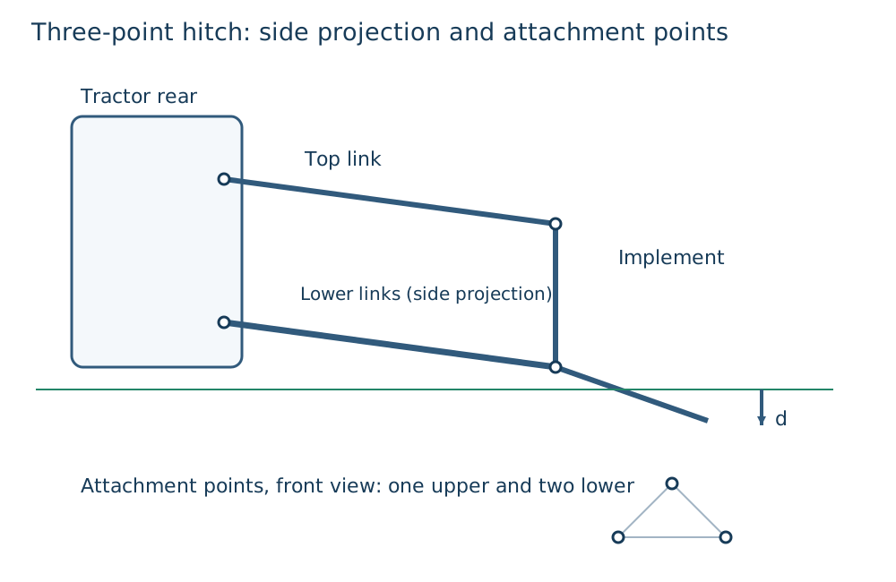
Figure: Created by Duskcoil. Actual link mounting points, implement, and control-valve configuration vary by model and task.
Position control holds the link position against a lever or target position. It's intuitive for uses like keeping a rotary tiller at a constant height, or raising/lowering it at the headland. Draft control, on the other hand, detects the draft resistance F_d transmitted through the top link or lower links, raising the implement slightly when resistance increases and lowering it when resistance decreases. It's used when a plow suddenly gets heavier entering a hard layer, to suppress engine stall or excessive slip while holding an average tillage depth.
A simple proportional-control image is
d is estimated tillage depth, d^* is target tillage depth, F_d is draft, and u is the amount of operation on the lift valve. In practice, soil flow, link play, implement lag, and body pitch all exist, so moving abruptly causes depth to oscillate. This is why position-only or force-only reliance isn't enough — position/draft mix control, top-link setting, and matching travel speed all need to be brought together.
Tillage depth is the distance from the ground surface to the blade tip, but the ground surface itself undulates, the tires or crawlers sink, and the front and rear wheels cross steps. Work-height control combines link angle, hydraulic cylinder position, rear-wheel slip, an implement's own ground-contact wheel, laser/ultrasonic/camera-based ground reading, and IMU attitude. For example, if you want seeding depth to be constant, the reference should be the relationship between the seeder's gauge wheel and the soil, not the tractor body's height.
8. Yield & Soil Sensors: A Map Includes the "Measurement Lag" Too
A tractor isn't a harvester, but at the time of seeding, fertilizing, and tilling it becomes the core that measures soil and work variability and links it to a later yield map. Representative examples are: relative soil characterization via electrical conductivity (EC), estimation of organic matter/moisture via near-infrared spectroscopy, hardpan detection via penetration resistance, and GNSS-tagged logs of fertilizer rate, seed rate, and tillage depth. High EC doesn't necessarily mean immediately fertile — it's affected by moisture content, salinity, clay content, and temperature. This must always be verified with soil sampling analysis and field observation.
Yield maps are, in most cases, built from the combine's grain flow meter or tank weigher, moisture meter, and GNSS. Overlaying this with the tractor's own work records lets you compare "did yield change the following year in a deep-tilled plot" or "was the variable-fertilization boundary appropriate." However, unless the time lag τ between the grain leaving the header and reaching the sensor is corrected, a value tagged to position (x(t),y(t)) actually belongs to (x(t-τ),y(t-τ)). Excluding turns, unloading, and sensor zero-offset is quality control that has to happen before a clean-looking map, not after.
| Sensor / record | Main quantity | Typical pitfall | How to connect it to a decision |
|---|---|---|---|
| Soil EC | Spatial variation in electrical conductivity | Confusing moisture/salinity/temperature with fertility | Stratifying sampling points, building hypotheses about drainage/soil texture |
| Penetration resistance | Soil hardness, hardpan depth | Value changes greatly with moisture condition | Candidate depths/zones for subsoiling |
| Three-point-linkage load / PTO torque | Work resistance, input load | Comparing without accounting for implement attitude or speed | Closed-loop control that limits travel speed/tillage depth |
| Fertilization/seeding log | Applied amount, position, time | GNSS dropouts, overlap, implement lateral offset | Verification of next season's prescription against yield |
| Combine yield/moisture | Spatial variation in yield, quality | Time lag, tilt, flow-rate calibration | Examining causal hypotheses against soil/input amount |
9. RTK-GNSS Autonomous Driving: Satellites Alone Don't Drive the Field
Standalone GNSS positioning has error that varies with satellite geometry, the ionosphere, and multipath. RTK (Real Time Kinematic) is a method that uses the carrier-phase difference from a base station or network correction to determine the rover's relative position with high precision. Under good conditions it can target centimeter-class relative accuracy, which helps straight-line assist that reduces overlap/skips between adjacent passes, positional repeatability for seeding and fertilization, and ridge-forming. Yanmar has announced that its 2026-launched YT4S/5S straight-line-assist specification comes standard with high-precision RTK-GNSS. Launch materials
But the antenna indicates one point on the body, not the implement's blade tip. Slopes, tire lateral slip, hitch play, and implement side-draft all offset the antenna's trajectory from the actual work line. So the control system measures, in addition to GNSS, roll/pitch/yaw via IMU, short-term motion via wheel speed, and machine state via steering angle, hydraulics, and link position. Cameras and LiDAR become auxiliary means for observing people, obstacles, ridges, and crop rows.
When comparing autonomous driving systems, at minimum "assists going straight," "follows an A-B line," "automatically turns at the headland," "raises/lowers and controls the implement," and "operates unmanned under supervision" should be distinguished. NARO has published a technology aiming for self-localization of agricultural vehicles on farm roads by integrating GNSS, AI-based road-recognition, and a method using poles as landmarks, weighted by reliability. Robust self-localization technology This shows that, once you account for places with poor satellite visibility or travel outside the field, a single sensor isn't enough.
The core of safety isn't just "the position matches." Field-boundary geofencing, emergency stop, confirmation of people/vehicles/waterways/power lines, safe stopping on communication loss, the order in which the implement is raised, and the role of a remote supervisor should all be decided as operations before deployment. The more automation is used to make up for labor shortages, the less ambiguous who does what during an exception should be.
10. Reading Current Product Examples
Because product names change with updates, region, and sales spec, this section doesn't assert a ranking of performance — it lists examples of design that can be confirmed on public pages. For purchase or deployment planning, cross-check cabin, transmission, tires/crawlers, implements, GPS correction service, and sales-region spec against the quote and manual even for the same model designation.
| Maker & product example | Key points readable from public info | Points to view engineering-wise | Official info |
|---|---|---|---|
| Kubota Agri Robo series | Deployed as an agricultural solution including robotic/autonomous driving and autonomous steering | Verify as a system including GNSS correction, supervision, and implement/field conditions | Agri Robo |
| Kubota M7 series, etc. | A lineup of tractors for large-scale work | Check traction, hydraulic flow, rear lift, and implement compatibility separately from horsepower | Tractor list |
| Iseki Japan / T.Japan, etc. | Deploys tractors across multiple horsepower bands for paddy and dryland farming | Compare turning, wet-paddy suitability, combination with rotary tillers, and presence of straight-line assist | Iseki tractors |
| Yanmar YT4S/5S | YT488S, YT498S, YT4104S, YT5114S launched June 2026. 88–114 PS; straight-line assist spec available | Read high output, I-HMT, hydraulic lift, and RTK-GNSS together as a set for heavy towing and precision straight-line work | YT4S/5S announcement |
| Yanmar YT225A/C, YT233A/C | Public examples of full-crawler spec. Lists 24.5/33.0 PS models | Evaluate low ground pressure and wet-paddy traversability against tradeoffs with mobility and maintenance | Product examples |
Deciding among Kubota, Iseki, and Yanmar based on maker name or peak horsepower alone is risky. First list out implement mass, required PTO output, the number and flow rate of hydraulic couplers, three-point-linkage category and lift capacity, the field's maximum slope and wet-paddy character, farm-road width, and storage location. On top of that, compare the cost of autonomous steering including correction signals, the local dealer's service network, and connectivity with existing implements. A tractor's value lies not in the unit itself, but in how many implements it can reliably run, and how much, throughout the year.
11. Latest Research: From Sensing to Closed-Loop Control
The focus of recent research has shifted from simply drawing a straight line with GNSS to deciding "at what speed, depth, and application rate should it run" based on soil and crop condition. It integrates draft, PTO torque, wheel slip, IMU, cameras, soil information, and work history, adjusting travel speed, gear, and linkage before reaching engine stall or excessive slip. This can be expressed as a constrained optimization.
Here v is travel speed, d is tillage depth, q is implement attitude, C is work rate, dot m_f is fuel consumption rate, and s is slip ratio. Because real-world controllers never fully know soil condition, and sensors carry noise and failures, rather than leaving everything to a learned model, upper limits on force/rotation/temperature, safe stopping, and manual intervention need to remain.
Image-based ridge/crop-row following, LiDAR obstacle detection, digital-twin-based soil-resistance prediction, and prescription updates from per-field work logs are also areas of ongoing research and field trials. But a result like "yield went up" can't be attributed to sensor adoption alone. Only by recording weather, variety, seeding date, drainage, disease, and operator adjustments alongside a control plot, and verifying over multiple years, does it become a basis for farm-management decisions.
12. Practical Checks for Operation and Maintenance
| Symptom | Check first | Engineering view |
|---|---|---|
| Front is light, hard to steer | Implement resistance, front ballast, link attitude | The hitch point is shifting load rearward. Casually increasing speed is dangerous |
| Rear wheels spin, poor fuel economy | Slip, 4WD, tire pressure, soil moisture, work depth | Distinguish insufficient traction from excessive required draft |
| Tillage depth varies | Position/draft settings, ground-contact wheel, link length, body attitude | Check whether the reference is the ground surface, force, or the implement side |
| PTO implement vibrates | PTO rotation, joint angle, guard, blade/shaft balance | Don't leave rotational unevenness and inertial load unaddressed |
| Autonomous steering weaves or drifts | RTK FIX status, antenna position, implement lateral offset, IMU | Body position and the position of the actual work result aren't the same |
Before starting, check oil level, coolant, leaks, tires or crawlers, wheel nuts, link pins, PTO guard, hydraulic hoses, lights, brakes, and implement securing. For clog removal, cleaning, or adjustment, stop the engine, remove the key, and confirm that rotating parts and hydraulics have completely stopped. Searching for a tiny hydraulic-hose leak by hand is also dangerous. A high-pressure fluid injection injury under the skin can look minor on the surface yet be an emergency, so seek medical attention immediately.
Summary
A tractor is the common platform of agricultural machinery, converting the output of an engine or electric motor into traction against the ground, PTO rotation, and the force and position of the hydraulic three-point linkage. Whether the work succeeds isn't determined by peak output alone, but by ground contact with the soil, slip, load transfer, PTO compatibility, link geometry, tillage-depth control, and field work efficiency.
The next evolution isn't just straight-line driving via RTK-GNSS. It lies in using position-tagged soil, yield, and load data to control travel speed, tillage depth, fertilizer rate, and implement attitude within constraints. Choosing between diesel, electric, and hybrid should also be evaluated not just by engine type, but including the field, work hours, soil compaction, refueling/charging, and connection with implements. The shortcut to understanding a tractor is, before asking "how many horsepower," to trace where force, rotation, hydraulics, and information are flowing.
Does more engine power always mean more drawbar pull?
Soil–tire traction limits usable force. Additional power may increase slip rather than useful pull.
References
- NARO: Robust self-localization technology for autonomous driving on farm roads
- NARO: GNSS use in smart agriculture
- Ministry of Agriculture, Forestry and Fisheries: Smart Agriculture Technology Catalog (Paddy/Upland Farming)
- Kubota: Tractor product list (confirmed September 3, 2026)
- Kubota: Agri Robo (confirmed September 3, 2026)
- Iseki: Tractors (confirmed September 3, 2026)
- Yanmar: Tractor lineup by series (confirmed September 3, 2026)
- Yanmar: YT4S/5S series launch (confirmed September 3, 2026)
Current step · 1 / 7 · Agricultural Machinery Engineering
Comments
Please log in to post a comment
No comments yet.