Contents — find the section you need
Background and reading guide
Background Basic frames, velocity and sensor terminology; use the reading guide for background.
Fundamentals · Explanations of principles, structure and trade-offs.
A hydraulic excavator's arm scoops several tonnes of earth and still stops smoothly. The secret behind generating hundreds of kN of force from a control lever the size of a human finger is a mechanism that circulates oil at high pressure and finely allocates flow through valves. Remember hydraulics as just a "strong motor" and you'll miss its heat generation, lag, leaks, and control difficulty. Understanding it as a robot means reading the energy source, fluid circuit, mechanical linkage, sensors, and control software as a single closed loop.
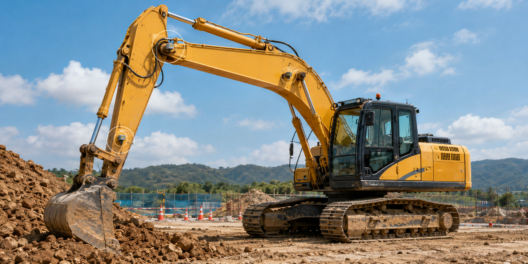 Hydraulic actuator context (concept illustration)
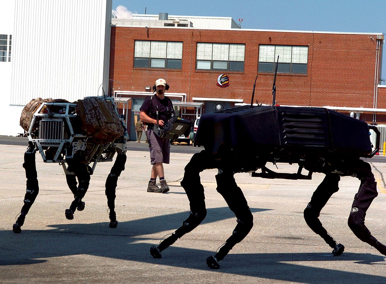 A hydraulically actuated robot in the field (BigDog)
Image: The concept illustration is a Duskcoil educational graphic (white circles are explanatory candidate sensor locations, not standard equipment on a specific manufacturer model). The field photo is Big dog military robots (U.S. Marine Corps photo by Lance Cpl. M. L. Meier, Public domain), Wikimedia Commons. A representative gasoline-engine-driven hydraulic quadruped, not the construction-machinery hydraulic circuits discussed in the text.

30-Second Summary
- By Pascal's principle, pressure p acts on cylinder area A and converts to force F=pA. In exchange for large force, flow Q determines speed.
- The pump generates flow, the relief valve protects the pressure ceiling, and directional/proportional valves distribute flow to each actuator. Not confusing pressure with flow is the first key point.
- Hydraulic motors and cylinders excel at high power density and shock resistance, but throttling losses and oil-temperature rise cut into efficiency. For electrification, a hybrid of an electric pump plus hydraulic actuators is often more realistic than "replace everything."
- Fusing pressure sensors, flow sensors, cylinder position sensors, and an IMU enables load estimation, digging-force control, and failure prediction. Sensor bandwidth and the compressibility of the plumbing determine closed-loop performance.
- In the field, design must include safety valves, load-holding valves, failsafes, and contamination control. A high-performance control law alone can't prevent accidents.
1. The Basics of Hydraulics: Pressure Is Force, Flow Is Speed
Pascal's principle states that pressure applied to a confined liquid transmits almost equally in every direction. In an idealized cylinder,
With pressure p at 20 MPa and piston area A=0.01\ \mathrm{m^2}, theoretical thrust is 200 kN. With flow Q=0.001\ \mathrm{m^3/s}, speed is 0.1 m/s. In short: increasing force needs large area and high pressure, and increasing speed needs large flow.
Ignoring losses, the hydraulic source's input power and the actuator's output are related by
When a valve throttles flow to slow the actuator down, the surplus pressure turns into heat. In mobile machines performing several operations at once, how you allocate demand that exceeds the pump's delivery determines both feel and fuel economy.
2. Reading a Typical Circuit
Figure 1 — The pump generates flow, the proportional directional valve distributes it to the cylinder, and return oil flows back to the tank. The relief valve is a safety valve that dumps to tank once the set pressure is exceeded.
Oil drawn from the tank is pressurized by the pump and returns after passing through a filter, control valve, and actuator. Oil isn't a perfect rigid body — piping and hoses expand, and bubbles mix in. As a result, closing a valve abruptly causes fluid hammer, producing pressure spikes and vibration. Orifices, accumulators, and ramp control shape the transient response.
3. Pumps, Valves, and Actuators
Pumps
Gear, vane, and piston pumps all exist; construction machinery mostly uses swash-plate axial-piston pumps, which handle high pressure and large flow. A variable-displacement pump changes swash-plate angle to adjust delivery, reducing throttling loss under light load. Combining pressure compensation (PC), load sensing (LS), and electronic control (EHP) lets the machine boost flow only when it's actually needed.
Valves
A directional control valve changes where oil is routed, and a proportional valve continuously controls spool opening. Servo valves have high bandwidth but are contamination-sensitive, so mobile machines more realistically pair a rugged proportional valve with feedback control. A check valve blocks backflow, and a counterbalance valve prevents a boom from falling under its own weight — safety functions that also need to exist outside the software.
Actuators
A cylinder produces linear motion, and a hydraulic motor produces rotary motion. A hydraulic motor's torque is approximately
where \Delta p is the differential pressure, D is displacement, and \eta_m is mechanical efficiency. An excavator's swing motor or travel motor requires thermal design that extends all the way through the reduction gear, brake, and planetary gear train.
4. Closed-Loop Control as a Robot
From the operator's lever input u, the signal propagates through valve opening, flow, cylinder speed, to link tip position. The minimal model for position control is the PID
but accounting for oil compressibility, friction, load variation, and valve deadzone, gains alone aren't enough. A common structure feeds forward the required flow up front, then corrects for load via pressure feedback.
Sensor roles break down as follows.
| Sensor | Main estimate | Use in control | Common failure mode |
|---|---|---|---|
| Pressure sensor | Differential pressure across both cylinder chambers | Thrust/ground-force/load estimation | Temperature drift, pulsation |
| Magnetostrictive/linear sensor | Rod position | Position/velocity control | Mud, water, mounting stiffness |
| Flow sensor | Actual flow downstream of valve | Speed control, leak diagnosis | Viscosity and bubble effects |
| IMU | Boom/vehicle attitude | Vibration compensation, dig trajectory | Separating gravity from acceleration |
| Force/torque sensor | Bucket reaction force | Contact/grasp control | Impact loads, overload |
In a hydraulic excavator, the boom, arm, and bucket cylinder positions are fused with the vehicle IMU, and bucket tip position is computed via forward kinematics. With link angles \boldsymbol{q} and Jacobian J(\boldsymbol{q}), tip velocity is
In research that estimates soil reaction force from pressure and holds a target digging force constant, overload can be suppressed even as ground hardness changes.
5. Estimating Efficiency and Heat Generation
The hydraulic system's overall efficiency is the product of the pump's, valves', piping's, and actuator's individual efficiencies. If pump outlet pressure is 25 MPa and flow is 200 L/min, input hydraulic power is
If mechanical output is 60 kW, roughly 72% is useful work; the rest turns into oil-temperature rise, friction, and leakage. When heat load exceeds the cooler's capacity, viscosity drops, internal leakage increases, and a positive-feedback loop drives efficiency down further.
Because hydraulic fluid viscosity varies with temperature, selection needs to account for more than just ISO VG grade — cold-start flowability, seal material, filter mesh size, and moisture contamination all matter. Managing cleanliness code (ISO 4406) and keeping contaminants out during oil changes is the cheapest way to reduce failure rate.
6. Real Examples in Construction and Agricultural Machinery
Komatsu and Caterpillar hydraulic excavators integrate control of engine speed, pump delivery, and valve opening to hold down fuel consumption in line with digging load. Machine-control specifications use GNSS, IMU, and cylinder position to display and constrain the bucket tip against a design surface, replacing an expert operator's feel with geometry and sensors.
Kubota and Yanmar tractors use the three-point linkage's lift cylinder and a draft sensor to adjust implement depth in response to tillage resistance. Because soil varies from place to place in agricultural machinery, mixed force/position control is more effective than fixed position control alone.
The interesting part of hydraulic systems is that the same principle gets a different "flavor" on different machines. An excavator prioritizes shock and large flow, a tractor prioritizes low-speed traction and fine adjustment, and a robot arm prioritizes low friction and high bandwidth. Even with identical pump capacity, valve spool characteristics, and control period, the optimal answer shifts with the machine's purpose.
7. Electro-Hydraulic Conversion and Current Research
- Independent metering: Controlling each valve's inlet and outlet independently reduces throttling loss, delivering pump pressure only to the actuator that needs it.
- Electro-Hydraulic Actuators (EHA): Placing a motor and small pump at each cylinder reduces long piping runs and central valves, enabling local regeneration and modularity.
- Hydraulic hybrids: Storing deceleration energy in an accumulator and reusing it during boom descent or swing stop. Higher power density than a battery, but with a shorter holding time.
- Learning-based load estimation: Estimating soil type or payload from pressure, valve commands, IMU, and work-camera footage. A monitor that falls back to a safe state outside the training distribution is essential.
- Predictive maintenance: Learning from time-series data of oil particulates, pump pulsation, and valve response lag to flag filter clogging or seal wear before a stop.
When evaluating electrification, compare not just battery capacity but peak output, cooling, regeneration, cold-weather performance, charging infrastructure, and hydraulic-actuator lifespan together. Even after moving fully to electric power, if the mechanism generating the arm's force is still hydraulic, fluid cleanliness and leak countermeasures remain.
8. Safety Design and Troubleshooting
Hydraulic pressure remains stored in an accumulator even after the engine stops. Before servicing, bleed off residual pressure per the specified procedure and put mechanical supports in place against dropping. Hunting for a hose pinhole leak by hand is dangerous — high-pressure oil can penetrate skin. Safety valves, load-holding valves, hose-burst valves, and emergency stops should all be mechanically redundant.
To narrow down the cause from a symptom, measure in this order.
- Tank oil level, contamination, bubbles, temperature.
- Pump inlet vacuum and outlet pressure, versus set point.
- Valve command value versus actual flow, spool sticking/deadzone.
- Consistency between both cylinder chambers' pressure and the position sensor.
- Mechanical linkage interference, pin wear, changes in external load.
Even the symptom "not enough force" can come from pump wear, relief-valve setting, internal leakage, sensor saturation, or control gain — any of them. Don't judge from a single pressure gauge; the basic approach is to take the energy balance from inlet to outlet.
Summary: A Hydraulic Robot Is a Coordinated System of Fluid and Software
A hydraulic system is a distributed system in which pressure handles force, flow handles speed, valves handle allocation, and sensors handle state estimation. High power density and shock resistance keep hydraulics strong today in excavators, tractors, aircraft, and surgical robots. On the other hand, heat generation, leaks, compressibility, and contamination constrain control and lifespan.
When reading about a new machine, it's worth checking: (1) how many MPa and L/min the pump supplies, (2) how much the valves throttle, (3) which sensors estimate force and position, and (4) which mechanical element returns the system to a safe state on failure. With these four points in hand, news about electrification or AI control can be evaluated including hydraulics' physical limits and implementation cost.
What if cylinder area doubles at equal pressure and flow?
Ideally, force doubles and speed halves. This exchanges force and speed rather than creating power.
References
Current step · 16 / 18 · Robotics Primer
Comments
Please log in to post a comment
No comments yet.