Contents — find the section you need
Background and reading guide
Background Basic frames, velocity and sensor terminology; use the reading guide for background.
Fundamentals · Explanations of principles, structure and trade-offs.
ArduPilot isn't a drone-only "autopilot app." From fixed-wing aircraft (Plane) and multicopters (Copter) to ground vehicles (Rover) and even submersibles/boats (hybrid configurations), it is an embedded platform that reads sensors, estimates state, issues actuator commands, and transitions to a safe state on failure. Before flying a vehicle, it's essential to understand estimation, control, communication, power, and the ground station together as a single safety case.
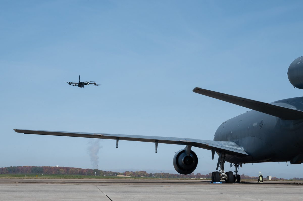 Example autonomous aircraft
Image: Skydio X2D inspecting aircraft (Mauricio Campino, public domain), Wikimedia Commons. Not an ArduPilot vehicle; it illustrates the onboard-compute and autonomous-flight context.

30-Second Summary
- ArduPilot fuses IMU, GNSS, magnetometer, barometer, and rangefinder data through an EKF to estimate attitude, velocity, position, and bias.
- Copter is centered on thrust allocation and attitude control, Plane on aerodynamics and energy management, and Rover on wheels/steering and path following — they don't share the same parameters.
- An inner angular-rate/attitude loop runs at high frequency, while an outer position/velocity/mission loop generates the targets. Verify PID signs and units on the real vehicle.
- MAVLink is the messaging protocol linking the vehicle to the ground station, companion computers, and peripherals. Comms loss, low voltage, GNSS loss, and geofence breaches are all handled via failsafes.
- Testing proceeds in stages: SITL, log replay, bench tests with propellers removed, tethered tests, and low-altitude tests. Even if the simulation succeeds, real-vehicle vibration, electromagnetic noise, and power sag are separate problems.
1. Architecture
Figure 1 — Sensors are fused through the EKF; the inner attitude/velocity control loop drives a mixer that outputs to motors and servos. MAVLink forms the boundary with the ground station and external computers.
The vehicle's main loop processes sensor acquisition, estimation, control, output, communication, and logging on a fixed cycle. High-rate IMU data predicts attitude, while GNSS, magnetometer, barometer, and external vision provide lower-rate corrections. When estimate quality degrades, rather than continuing to chase the target, the controller switches to a safe action — hold, return, or land.
2. State Estimation via EKF
One example state vector is position p, velocity v, attitude R, and gyro/accelerometer bias b_g,b_a. Prediction comes from the IMU, and updates come from external observations.
Here a_m,\omega_m are the measured values, g is gravity, and [\cdot]_{\times} is the cross-product matrix. The EKF propagates the covariance P, and temporarily rejects a sensor whenever its observation residual (innovation) falls outside the expected range — a mechanism for not blindly accepting magnetic interference or multipath GNSS.
Vehicle vibration adds high-frequency content to the accelerometer, destabilizing both estimation and control. Frame stiffness, propeller balance, dampers, and filter latency need to be tuned on both the mechanical and software sides. Overlaying the vibration spectrum from the log with the EKF's innovation at the same timestamp makes it easier to isolate the cause.
3. Control in Copter, Plane, and Rover
Copter
A multicopter generates attitude torque from total thrust T and each motor's rotation rate. Approximately,
where the mixer allocates the roll, pitch, yaw, and throttle demands across each motor. Outside the attitude-angle loop sits a velocity/position loop, which monitors thrust margin against wind and payload changes.
Plane
A fixed-wing aircraft flies using wing lift and drag, airspeed, angle of attack, and energy state. It turns via roll angle and adjusts speed/altitude via pitch, so multicopter gains can't be reused directly. Automatic landing requires dedicated testing that accounts for wind, runway, and sensor latency.
Rover
Rover fuses wheel speed, steering angle, GNSS, compass, LiDAR, and similar sensors to follow waypoints and speed targets. Because wheel slip and slopes throw off Dead Reckoning, covariance and re-localization are designed the same way as the odometry covered in the robotics-dead-reckoning article.
4. Missions and MAVLink
A mission is a sequence of commands — waypoints, speed, altitude, camera trigger, landing, and so on. MAVLink is a small binary message protocol that exchanges heartbeat (HEARTBEAT), position, attitude, parameters, mission data, and command acknowledgments. SITL and the ground station connect over UDP; on real hardware, the radio link's latency, bandwidth, encryption, and authentication must be evaluated.
When automating a mission, don't advance to the next command without waiting for acknowledgment. Define ACK, timeout, retry, cancel, and the resume position after a power cycle. Communication should never be the single point of failure for control — design so the vehicle can return and land safely even if the ground station drops out.
5. Failsafes and Safety Testing
Detect low voltage, RC link loss, degraded GNSS quality, EKF faults, geofence breaches, and motor failure, and transition to a behavior appropriate to the vehicle type. Copter's "Return to Launch" isn't always the safe choice — in strong wind, near obstacles, or with an unconfirmed home position, landing or holding may be more appropriate. Once thresholds are set, actually test crossing those thresholds in a low-risk environment.
Testing should be staged: SITL → hardware-in-the-loop → propellers removed → tethered → low altitude → operational altitude. Run logged fault-injection tests — cutting power abruptly, shielding the GNSS antenna, severing communications, removing a single sensor. Flight authorization, local aviation law, privacy, and radio regulations are as much a part of the technical requirements as anything else.
6. A Recommended Order for Tuning Parameters
- Confirm sensor orientation, calibration, timing, and supply voltage.
- With the vehicle restrained, measure gyro/accelerometer/compass bias and vibration.
- Tune the inner attitude loop starting from small gains, watching for saturation and oscillation.
- Add the velocity/position/altitude loops, and evaluate tracking under varying wind and payload.
- Run a full end-to-end test of missions, failsafes, restarts, and logging.
Copying gain values from another vehicle won't produce stability if the propellers, moment of inertia, thrust margin, or sampling period differ. Overlay target, measured value, output saturation, and innovation in the log to see which loop is introducing lag.
7. Current Use and Research
ArduPilot is used across fields with many vehicle types — agricultural spraying, surveying, disaster assessment, research VTOL, autonomous boats. Some configurations send targets from a companion computer over MAVLink and feed ROS 2 or computer-vision estimates in as auxiliary observations. Research is progressing on visual navigation, multi-sensor fault diagnosis, learning-based wind estimation, and multi-vehicle coordination — but it's still best practice for the final output to pass through the existing limits and failsafes.
Summary
The essence of ArduPilot is unifying sensor fusion, hierarchical control, mission execution, communication, and failsafes into a single embedded system. Before writing code that moves the vehicle, specify the estimated state and coordinate frames, the control period, output limits, and the transitions on failure. Make use of SITL and logs, and stage safety testing carefully on the real vehicle, and open-source software can carry a project from research into real operation.
Is entering a route sufficient for autonomous flight?
Vehicle setup, estimation, control, and failsafes must work together. Separate route planning from conditions for executing commands.
References
Current step · 17 / 18 · Robotics Primer
Comments
Please log in to post a comment
No comments yet.