Contents — find the section you need
Background and reading guide
Background Basic force, motion and energy terminology; use the linked background explanations.
Fundamentals · Explanations of principles, structure and trade-offs.
A combine harvester combines three operations into a single machine: cutting the crop, threshing the grain out of the panicle, and separating the grain from the straw and chaff. Japan's familiar "head-feeding" type — common in rice cultivation — feeds only the panicle end of the rice into the threshing section, leaving the long straw outside the machine. This seemingly simple division of labor is in fact a design refined to match Japan's rice-cultivation system, which includes muddy paddies, small field plots, straw utilization, and downstream drying/conditioning processes.
This article focuses on the internal material flow that's hard to see from the operator's seat. A combine's capability isn't determined by horsepower or the number of rows alone. It's a mobile separation factory that simultaneously handles crop volume, moisture, lodging, ground undulation, dwell time inside the machine, airflow, and "how much grain fell on the ground." Unless otherwise noted, all specs, prices, and feature descriptions in this article are based on public information confirmed as of September 3, 2026.
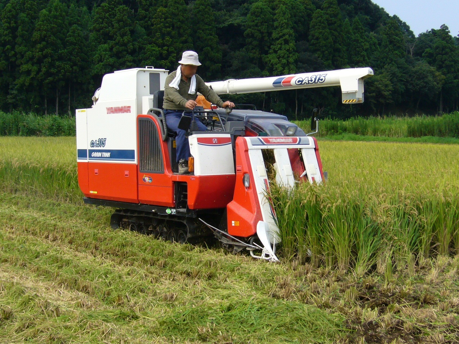 Rice combine in Katori, Japan
Image: Rice-combine-harvester, Katori-city, Japan (katorisi, CC BY 3.0), Wikimedia Commons. A 2007 field photograph, not one of the current models discussed below.

30-Second Summary
- A head-feeding combine cuts the rice at the cutting section, then a feed chain carries only the panicles to the threshing cylinder. The cylinder removes the grain, and an oscillating shaker and winnowing fan airflow separate grain, rachis branches, and straw fragments, sending clean grain to the grain tank.
- Japan's head-feeding type evolved from national prototype research in the 1960s into commercial machines. The background is rice-farming-specific requirements: large ordinary-type combines are hard to use in wet paddies with small plots, and there's a desire to keep the rice straw intact rather than chopping it up. This isn't simply "a shrunk-down version of the world-standard machine."
- Losses are broken down into pre-harvest shattering, header loss, incomplete threshing, and separation-stage scatter. The total loss rate is evaluated as the mass of grain that couldn't be recovered divided by the mass of grain that should have been obtained. Improving efficiency isn't just about raising travel speed — it's about raising throughput while treating this rate as a constraint.
- Yield sensors use flow rate or tank weight; moisture meters use electrical resistance; a representative quality indicator is near-infrared-estimated brown-rice protein content. Linking GNSS position and time turns this into mesh maps of yield, moisture, and protein. But ignore time lag, tilt, and calibration, and the map will look plausible while being wrong.
- Among current large-scale head-feeding models, Kubota's Agri Robo DR6130A is a 6-row, 130-horsepower machine; Yanmar's YH6135,A / YH7135,A are 6/7-row, 138-horsepower machines; and Iseki's HJ6135 / HJ7135 form a 6/7-row model group. Autonomous steering isn't a story of "unmanned equals safe" — it's an operating system that includes human supervision, field boundaries, unloading, and obstacle detection.
First, a Distinction: Ordinary-Type vs. Head-Feeding
An ordinary-type (whole-crop-feeding, full-swath) combine cuts the entire crop at the header and feeds the stalks, panicles, and leaves together into the threshing/separation section. This format developed for the large, dry fields of North American wheat, corn, and soybeans, with wide headers and large throughput. A head-feeding combine, by contrast, holds the base of the rice stalk with a feed chain and passes only the panicle portion into the threshing chamber. Because the long stalks exit to the straw-discharge section outside the machine, the volume of straw entering the threshing and cleaning chambers is dramatically reduced.
This difference isn't merely about how the crop is fed in. Because ordinary types handle large volumes of straw, they need a large separation area and high drive power, but in exchange they can switch crop types easily. Head-feeding types must carry the rice while keeping its posture, which makes pickup and conveying design difficult under lodged conditions — but they can confine the threshing chamber's load to the panicle alone. That suits turning in the relatively small plots of paddy fields, distributing ground pressure with crawler tracks on wet soil, and leaving the straw in whatever form is needed.
Why Did the Head-Feeding Type Originate in Japan?
"Originated in Japan" means that the lineage of practical head-feeding combines — which integrate cutting with threshing and separation of only the panicle — arose from Japan's rice-cultivation conditions and was rapidly refined and spread domestically. According to a report from the predecessor of NARO (National Agriculture and Food Research Organization), automatic threshers and "standing-crop threshing head-feeding combines" were first prototyped in 1960; in 1962 multiple manufacturers researched combinations of reapers with automatic threshers; and the first 100 units were commercialized in 1966. By 1971, roughly 100,000 units were reportedly in use. NARO research report on improving head-feeding combine performance
There are four background factors. First, paddy fields are softer than dry fields, and field plots were small at the time. Rather than bringing in a huge ordinary-type machine, it was more practical to use a lightweight crawler machine that could turn in narrow headlands. Second, rice straw has value as livestock bedding, compost, and for binding/drying, so handling only the panicle fit better with downstream processes. Third, Japanese paddy rice tends to carry variability in high moisture, lodging, and varietal differences, and a mechanism that reliably held and fed the panicle was advantageous for both quality and loss. Fourth, there was strong demand to labor-save the entire chain of transplanting, harvesting, and drying/conditioning, letting farm-machinery makers and public research institutions repeat cycles of experimentation, mass production, and improvement.
So calling the head-feeding type merely a "small combine" is inadequate. By not bringing straw into the machine, it's an architecture adapted to a cultivation system — one that changes the required separation area, airflow, reprocessing, and power allocation. Even today, the right-front operator's seat and continuously variable transmission via hydraulic motor persist as the basic layout of head-feeding machines. Iseki — the evolution of farm machinery
What Happens Inside the Machine: Four Stages
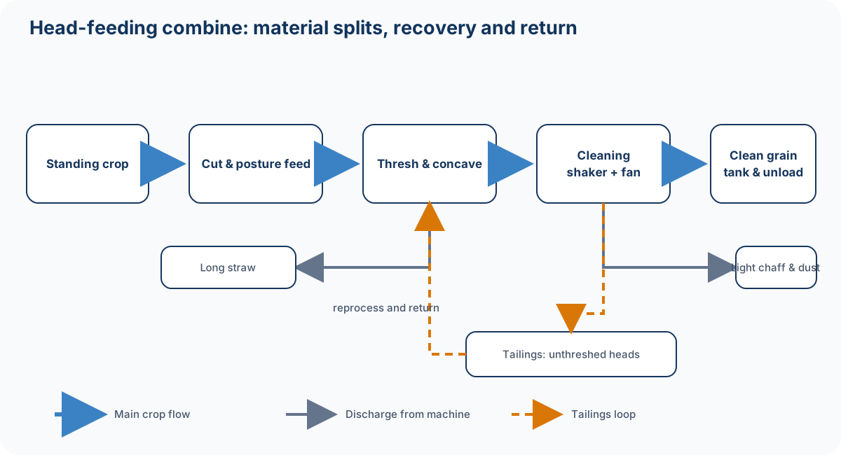
Figure: Created by Duskcoil. Arrows show the main material path; in tailings (2nd) processing, some unseparated material returns to the cleaning section.
1. Cutting: Reading the Boundary Between the Ground and the Rice
The front dividers separate adjacent hills, and the divider defines the edge of the working width. A pickup mechanism lifts lodged rice, and the intake mechanism conveys the base of the stalk. The reciprocating cutting blade and fixed blade shear the stalk, and the conveyor chain and star wheels direct the panicle tip toward the threshing section. Here, the difficulty isn't so much "cutting" as feeding the rice in the correct posture afterward without dropping it. Lodged rice, tangled weeds, and machine-attitude changes caused by mud all invite pickup failure and header loss.
Cutting-height control is a function that keeps the cutting section from sinking too low (which would suck in mud and short stalks) while still not leaving panicles uncut. Ground-tracking combines contact sensors, the cutting section's load/angle, and body-leveling control. In head-feeding machines, the height at which the stalk base can be handed off to the feed chain is also a constraint, so this isn't simply "a fixed height above the ground" — it's control that incorporates crop posture, row spacing, lodging direction, and body roll. Cut too high and you get uncut crop and header loss; cut too low and you get more soil and stalk intake, blade wear, and clogging.
2. Threshing: Removing Grain from the Panicle Without Breaking It
The feed chain grips the stalk and carries it, passing the panicle section between the rotating threshing cylinder and the concave. The threshing teeth's striking, rubbing, and centrifugal action removes the grain from the rachis branches. The dislodged grain and small straw fragments fall downward through the concave, while the larger stalk proceeds to the straw-discharge path. Cylinder rotation speed, chain speed, tooth shape, and concave opening determine the tradeoff between threshing rate and grain-damage rate.
Stronger threshing doesn't necessarily work better on dry crops. Push the rotation speed too high and grain cracking, breakage, and straw fragmentation all increase, making cleaning heavier. In wet rice, panicles are harder to loosen, so threshing load rises even at the same travel speed. The reason current machines correct travel speed and cleaning conditions by monitoring engine load, cylinder loss, and shaker loss is precisely to avoid leaving this variability entirely to the operator's intuition.
3. Cleaning: Using Differences in Grain Motion, Not Weight
The mixture right after threshing contains grain, rachis branches, short straw, unthreshed panicles, and fine dust. The oscillating shaker breaks up the mixture with a back-and-forth motion, forming layers. The winnowing fan's airflow blows the lighter straw fragments rearward, while relative specific gravity and air resistance let the comparatively heavy grain fall through the sieve. In practice it isn't simply "only the heavy things fall" — it's a probabilistic separation involving grain size, shape, initial velocity, layer thickness, wind speed, and sieve opening.
Unthreshed panicles and large rachis branches mixed in with the grain are collected by the tailings (2nd) auger and loosened in the tailings-processing cylinder before being returned to the front of the shaker. This recirculation improves separation accuracy, but returning too much increases the amount of material sitting in the system and overloads the shaker. Iseki states that its HJ6130/7130 combines a large-diameter, long threshing cylinder (publicly stated as 446 mm diameter, 1,250 mm width) with tailings processing. Iseki — Operability and high precision
4. Storage & Unloading: "Carrying" the Grain Is Also Part of the Harvest Operation
Cleaned grain is lifted to the grain tank by a horizontal auger and an elevator auger. Once the tank is full, the unloader (discharge auger) swings and extends to unload into a truck or flexible container bag. If cutting can continue during unloading, uptime improves, but positioning relative to the receiving vehicle, contact risk, mud, and visibility of the auger tip become new safety concerns. When "autonomous operation" is said to include "unloading is also automated," it's worth checking whether this vehicle-coordination piece is actually included.
Reading the Cross-Section: Power, Material, and Information Take Separate Paths
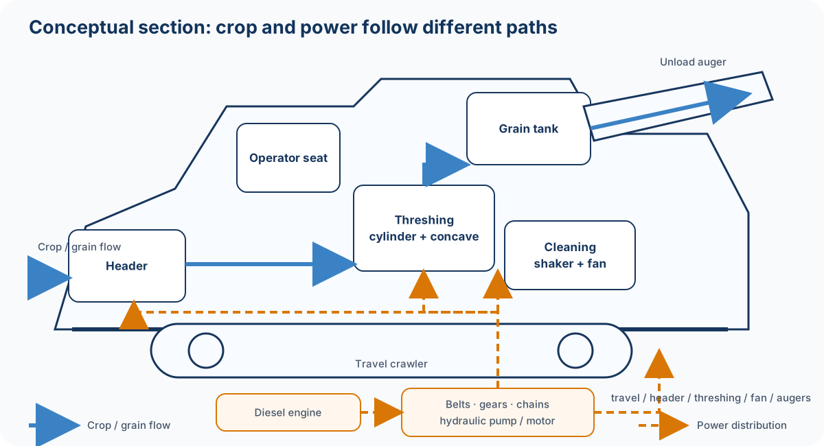
Figure: Created by Duskcoil. Actual component layout varies by model. This cross-section is a conceptual diagram illustrating the key point of the head-feeding design: only the panicles enter the threshing section.
Engine output is distributed via belts, gears, chains, and hydraulic pumps to the travel crawlers, cutting section, threshing cylinder, fan, and augers. The flow of the crop and the flow of power don't line up one-to-one. For example, just slowing travel speed reduces the input volume per unit time, but if cylinder and fan rotation are maintained, cleaning margin increases. Conversely, dropping engine speed too far saves fuel but can starve airflow volume and threshing peripheral speed, increasing loss. The goal of control isn't "always maximum RPM" or "always minimum fuel consumption" — it's minimizing total work cost under constraints on quality, loss, and throughput.
Handling the Loss Rate as an Equation
Let M_0 be the mass of recoverable grain actually present in the field, and M_{\mathrm{tank}} the mass recovered into the grain tank. If the mass that couldn't be recovered during the operation can be measured or estimated, the total loss rate L_{\mathrm{total}} is
In the field, directly weighing the full M_0 is impractical, so losses are sampled by cause.
Here L_{\mathrm{pre}} is shattering/lodging loss that occurred before the operation, L_{\mathrm{header}} is loss during cutting and conveying, L_{\mathrm{thresh}} is unthreshed grain lost on the straw-discharge side, and L_{\mathrm{sep}} is loss on the shaker/chaff-discharge side. Strictly, double-counting between these paths must be avoided, but this breakdown is effective for setting adjustment priorities. Collect a small sample of discharged straw and count unthreshed panicles, take a framed sample of grain on the chaff-discharge side, and normalize mass per area by yield.
The machine's input rate (feed rate) can be approximated as the product of dry-matter/grain quantity per unit area Y, effective cutting width w, and travel speed v.
However, at high moisture, long stalks, and under lodging, even with the same grain yield Y, the volume of straw being handled and its entanglement increase, so the tolerable \dot M decreases. When an operator decides "today I'll cut slower," it isn't about speed itself — it's feed-rate control that keeps shaker layer thickness, cylinder load, and loss-sensor readings from exceeding their tolerable range.
How to Measure Yield, Grain Quality, and Moisture
The value of collecting position-tagged data during harvest isn't limited to knowing average yield. Even within a single field, differences in soil, fertilization, water management, lodging, and disease exist, letting next season's fertilization, variety choice, and drainage improvements be considered one level more finely than a "field average." But sensors aren't a magic box — you need to understand what's being measured, where, and at what point in time.
| Information | Representative detection principle | What's corrected/calibrated | Example use |
|---|---|---|---|
| Yield | Grain flow rate, or tank weight via load cells | Tilt, zero point, lag between intake and measurement, variety | Yield mesh maps, fertilization design |
| Moisture | Multi-grain electrical resistance, dielectric constant, etc. | Temperature, grain temperature, variety, flow rate, contact condition | Drying plans, quality control |
| Grain-quality-related | Reflectance near-infrared spectroscopy estimating brown-rice protein content | Calibration curve, grain temperature, moisture, contamination of the optical window | Protein/yield maps, verification of fertilization |
| Position/attitude | GNSS, IMU, travel speed, heading | Positioning error, lag time, antenna position | Assignment to mesh, travel trajectory |
In the rice/wheat yield combine developed by NARO, tank weight measured by load cells was used for yield measurement, a multi-grain electrical resistance method was used for moisture, and tank weight was corrected with a tilt sensor. NARO — Rice/Wheat Yield Combine A biological-information-measuring combine has also been presented, with a configuration that simultaneously handles grain mass, grain moisture, brown-rice protein content via reflectance near-infrared, and straw mass/moisture. NARO — Biological Information Measuring Combine
The term "taste sensor" is easily misunderstood. In most cases, the sensor doesn't directly measure a person's sense of "deliciousness." It estimates protein content — one indicator related to rice's palatability — via near-infrared, and links it with yield, moisture, and position. Because palatability is determined by multiple factors including variety, milling, cooking, moisture, amylose, and protein, the protein value alone shouldn't be read as an absolute palatability score. Even so, it's a powerful tool for understanding relative variation within a field and verifying whether nitrogen fertilization is under- or over-applied.
It's also a mistake to simply link position \mathbf p(t) and sensor output q(t) at the same instant. There's a dwell time \tau between cutting and the moment the material passes through threshing, elevation, and the sensor. In mapping, q(t) is conceptually assigned to \mathbf p(t-\tau), and data at plot edges and during turns is further excluded. \tau isn't necessarily constant — it varies with crop volume and flow within the tank. This is why sensor research cites time lag, machine tilt, low flow rate, and durability as challenges. NARO research report
Kubota states that the DR6130A comes standard with taste/yield sensors and can link taste/yield mesh maps to KSAS. According to the compatibility list, the DR6115/DR6130 and DR575/DR595 also have standard or optional settings depending on spec. Kubota — Compatible machine list
Comparing the Public Specs of Current Models
The table below isn't a side-by-side of every catalog spec — it extracts, within the same category of "large-scale rice head-feeding combine," the indicators that can be reliably read from public pages. Prices vary by spec, region, and options, so purchasing decisions should be reconfirmed with a dealer quote. The reference date is September 3, 2026, and Kubota's price page explicitly states it reflects prices as of July 1, 2026.
| Maker & Model | Rows / Max output | Key publicly stated features | Publicly stated price, etc. | Official URL |
|---|---|---|---|---|
| Kubota Agri Robo DR6130A | 6 rows, 130 hp | Manned autonomous operation, taste/yield sensors standard, direct KSAS communication | Manufacturer's suggested retail price ¥26,059,000 (tax included) | Product list / DR6130A |
| Yanmar YH6135,A | 6 rows, 138 PS (101 kW/2,200 rpm) | Autonomous steering, yield-mapping spec, body-leveling control, etc. depending on spec | Suggested retail price per the 2026 Summer listing example, ¥25,938,000 (tax included, QXJPUAM2) | Product page / EXPO listing |
| Yanmar YH7135,A | 7 rows, 138 PS | Same lineage as above. Combines multiple autonomous modes after registering the perimeter on the first lap | Suggested retail price per the 2026 Summer listing example, ¥27,390,000 (tax included, QXJPUAM2) | Product page |
| Iseki Japan HJ6135 / HJ7135 | 6 rows / 7 rows | New Japan series. Check model designation and spec sheet for details | Price via official model search / confirm with dealer | FY2026 first-half new products |
| Iseki Japan HJ6130-Z | 6 rows | GPS-based straight-line assist, automatic A/B point acquisition, reverse assist | Public product page including a previous-generation model. Check sales status/price separately | HJ6130-Z |
A point to watch when comparing: "higher horsepower" doesn't mean "harvested area per hour scales up proportionally." Actual field efficiency is determined by effective cutting width, travel speed, time spent turning/unloading/refueling, speed reduction under lodging or wet-field conditions, and even the receiving capacity of the drying facility. Yanmar states that after manually registering the perimeter on the first lap, the YH6135,A/YH7135,A can operate roughly 90% of a field's area under autonomous steering. Launch materials This shouldn't be read as a guarantee that "90% is unmanned in any field" — it should be read as a description of the operating scope, premised on boundaries, crop conditions, and supervision.
What Does Autonomous Operation Actually Automate?
Comparing "autonomous operation" as a single word drops the substance of the technology. At minimum, it should be broken into: (1) steering that holds a straight line, (2) detecting the uncut side and following it with the cutting section, (3) turning in the headland, (4) maintaining cutting height and body attitude, (5) handling unload behavior and vehicle position when the tank is full, and (6) stopping safely in response to people, obstacles, or communication anomalies.
GNSS is strong as a positional reference over long straight runs, and RTK correction can target centimeter-class relative accuracy. But rice row alignment, field boundaries, drainage ditches, ground steps, and lateral slip from mud can't be read from satellites alone. So GNSS, IMU, wheel/crawler speed, cameras, and crop sensors are fused, with steering and the working components separately closed-loop controlled. Iseki's HJ6130-Z straight-line assist automatically acquires A/B points during operation and displays GPS sensitivity and deviation from the reference line, with its main focus being reduced steering burden. Iseki — HJ6130-Z
In safety design, whether a person is aboard, whether someone is supervising nearby, who handles emergency stops, and how a geofence that keeps the machine within the field is configured matter just as much as the machine's own performance. Harvest season extends work into dusk, dust reduces visibility, and unloading alongside a truck while driving happens too. Automation can reduce fatigue and the need for skilled operation, but it doesn't reduce exception handling to zero. The manufacturer's operating manual, regional safety guidance, and pre-operation field inspection take priority.
Diesel's Role and Where Electrification Stands Today
The reason large combines' primary engine remains predominantly diesel is sustained high load over long durations, fast refueling, energy density per unit weight, and the peak power needed to simultaneously drive travel, threshing, cleaning, and hydraulics. The engine isn't just for driving — it's also the power plant that keeps the cylinder, fan, hydraulic pumps, and augers rotating steadily. Because load changes sharply with crop volume, electronically controlled fuel injection, turbocharging, aftertreatment, and rotation-speed control are used together to satisfy both torque and emissions regulations.
However, "electrification" doesn't necessarily mean "replace the primary engine with a battery right now." What's advancing first in farm machinery is electrification of auxiliary equipment, reduction of idle time, battery-based peak assist, electric actuators for implements, and small chargeable/swappable machines. Fully battery-electrifying a large head-feeding combine for all-day operation faces severe constraints: the required energy, charging infrastructure, high-voltage safety under mud and dust, and soil compaction from added weight. Even while still using diesel, reducing hydraulic losses and cutting unnecessary reprocessing at the optimal travel speed is itself a meaningful decarbonization step.
Meanwhile, electrification is genuinely progressing. Among its FY2026 first-half new products, Iseki includes an electric riding mower, the SXGE2, aimed at the European market, equipped with a 7.92 kWh lithium-ion battery. Iseki — FY2026 first-half new products The application and scale differ from a combine, but it's a real-world example of farm machinery accumulating experience with batteries, BMS, environmental durability design, and charging operations. Rather than the future combine suddenly converging on one of diesel, series hybrid, swappable batteries, biofuel, or fuel cells, it's more likely to start from coexistence tailored to operating hours, field conditions, and power supply.
Latest Research: Treating High-Moisture Rice as a "Speed Control Problem"
An important recent direction is feeding sensor information back into control during the harvest itself, not just building a post-harvest map. NARO, Iseki, and University of Miyazaki, among others, announced in 2026 a travel-speed control method for high-moisture paddy rice (grain moisture 25% or above), using torque as an indicator of threshing load and a grain-flow sensor as an indicator of cleaning/chaff-discharge loss. When throughput is high, travel speed is reduced; when there's margin, it's increased — aiming to achieve both work efficiency and reduced loss under high-moisture conditions. NARO press release
What this research shows is that combine automation isn't just "AI that turns the steering wheel." With input x=[\text{torque},\text{loss flow rate},\text{moisture},\text{attitude}] and travel speed v as the manipulated variable, the control is conceptually close to a constrained optimization
where L is loss and T is threshing load. On an actual machine, accounting for model error and sensor failure means not changing speed abruptly, moving to a safe low speed or stopping under abnormal conditions, and setting upper limits per crop condition. Camera-based lodging estimation, digital-twin-based clog prediction, and predictive travel speed using field maps and yield history are research themes that extend this framework.
Checkpoints for Operation and Maintenance
To avoid leaving harvest quality entirely to the machine, inspect the cutting blade, pickup tines, feed chain, threshing teeth, concave, shaker, fan, augers, and crawlers before operation. A worn cutting blade increases cutting resistance and the risk of pull-in accidents; a clogged concave changes threshing/cleaning conditions; and straw clogging the radiator invites overheating. After making a setting change, don't judge by speed alone — actually observe the straw-discharge and chaff-discharge sides to confirm loss and contamination.
| Symptom | First suspect | Approach to adjustment/verification |
|---|---|---|
| Panicles left behind, hills knocked down | Pickup, dividers, cutting height, travel speed | Adjust to lodging direction, don't lower the cutting section too far, verify hand-off |
| Many unthreshed panicles in discharged straw | Cylinder, concave, chain speed | Check moisture/variety and correct for under-threshing; don't raise rotation speed too far |
| Straw fragments mixed in with grain | Airflow, sieve, tailings processing | Isolate insufficient/excessive airflow, sieve opening, and overload |
| Grain present on the chaff-discharge side | Fan airflow, shaker load, travel speed | First reduce input volume, then check airflow, attitude, and shaker clogging |
| Yield map shows streaks or spikes | Time lag, calibration, GNSS, turn data | Verify the measurement system with zero and weight checks, filter edges and turns |
Operator safety is also part of performance. Don't skip the basics: never clean with the covers over rotating parts, belts, or chains removed; always confirm the engine and rotation have stopped before clearing a clog; don't force sharp turns on slopes or near irrigation channels; and keep the unloading auger away from power lines and people. The manufacturer's operating manual and warning labels for the specific machine always take priority over the general statements here.
Summary
A head-feeding combine is a machine that runs cutting, threshing of only the panicle, cleaning via airflow and shaking, and storage/unloading into a tank as a continuous sequence. The configuration born within the constraints of Japan's paddy fields, rice straw, and small plots changed body dimensions, throughput, traversability, and downstream processes — all from a single choice: not bringing large volumes of straw into the threshing chamber.
The center of next-generation development isn't a horsepower race alone. Travel-speed control that treats the loss rate as a constraint, position-tagged measurement of yield, moisture, and protein, steering that uses GNSS and crop information, autonomous operation that includes supervision and safety, and gradual electrification building on diesel efficiency improvements — machinery, measurement, control, and farm-management data all tie together within one machine. The shortcut to understanding a combine isn't the row count visible from outside — it's tracing which material travels which path, in what time, to where.
Does faster cutting always increase harvest throughput?
Threshing and separation can become bottlenecks. Check grain losses and blockages across the whole process rather than increasing travel speed alone.
References
- Kubota: Combine/Binder/Harvester list (confirmed September 3, 2026)
- Kubota: Agri Robo DR6130A (price reference date: July 1, 2026, as stated on the page)
- Yanmar: YH6135 / YH7135 (confirmed September 3, 2026)
- Yanmar: 2026 SUMMER Head-Feeding Combine (confirmed September 3, 2026)
- Iseki: FY2026 first-half new products (confirmed September 3, 2026)
- Iseki: Japan HJ6130-Z (confirmed September 3, 2026)
- NARO: Research on improving head-feeding combine performance
- NARO: Travel-speed control technology for combines adaptable to harvesting high-moisture paddy rice
- Ministry of Agriculture, Forestry and Fisheries: Smart Agriculture Technology Catalog (Paddy/Upland Farming)
Current step · 5 / 7 · Agricultural Machinery Engineering
Comments
Please log in to post a comment
No comments yet.