Contents — find the section you need
When adding sensors makes localization worse, the filter is not the only suspect. Measurements cannot be compared directly if their times, frames or units differ. Check each input, then the boundaries where it enters fusion.
Fix the diagnostic order
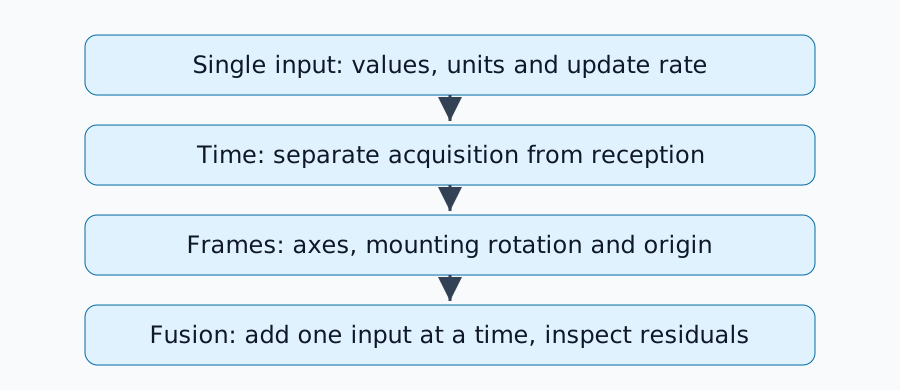
Reuse a short log and inspect wheels alone, IMU alone, then both. Changing the floor or driving speed at the same time obscures the cause. Review the principles in sensor fusion fundamentals.
Timing error becomes motion error
At a constant 1 m/s, a 50 ms timestamp error creates a 1\times0.05=0.05 m apparent displacement. At 90 degrees/s, the same error creates 4.5 degrees of rotation mismatch. These are constant-motion calculations, not recommended tolerances.
Determine whether a message timestamp denotes sensor acquisition or driver reception. A fixed transmission delay may be manageable with correct acquisition timestamps; clocks that disagree across hosts are a different problem. A longer queue does not correct clock offset. During replay, make all relevant nodes use the same simulation-time configuration.
Check axes and origins
ROS body frames normally use x forward, y left and z up; camera optical frames use z forward, x right and y down. Check conventions in REP-103. Renaming a frame does not rotate its values.
Transform a sensor point using p_b=R_{bs}p_s+t_{bs}. Both rotation and translation matter. The inverse translation is -R^Tt, not simply -t. Record whether calibration maps sensor to body or body to sensor.
Mounting offsets also change motion
For a rigid body, velocity at the sensor is v_s=v_b+\omega\times r. With a perpendicular 0.2 m offset and angular velocity 1 rad/s, the velocity difference is 0.2 m/s. A sensor away from the rotation center moves even during an in-place turn.
Include turns as well as translation in diagnostics. Full extrinsic calibration requires sufficiently informative motion; straight driving alone may not identify every degree of freedom. Compare frame responsibilities with REP-105.
Inspect residuals and covariance last
| Symptom | Hypothesis | Compare next |
|---|---|---|
| Error grows with speed | Timing mismatch | Same route at different speeds |
| Error grows during turns | Axes, offset or timing | Stationary, straight and left/right turns |
| Estimate jumps when adding an input | Frame, units or overconfidence | Raw input and prediction residual |
| Slow drift | Bias or slip | Raw averages and observable directions |
A residual is the difference between observation and prediction. Smaller covariance increases trust; it does not correct wrong axes or timestamps. Treating position and velocity derived from the same encoder as strongly independent observations can also overcount information. Inspect input selection and frame handling in the official robot_localization implementation.
Confirm one cause at a time
Change one setting, compare the same log, then confirm with a new run. Plausible stationary values do not rule out motion-dependent synchronization or mounting errors. Before SLAM evaluation, record timestamp semantics, units, TF publishers and calibration direction together.
Comments
Please log in to post a comment
No comments yet.