Contents — find the section you need
Background and reading guide
Background Basic force, motion and energy terminology; use the linked background explanations.
Fundamentals · Explanations of principles, structure and trade-offs.
When people think of a crane's performance, "how many tonnes can it lift" comes to mind first. But even on the same machine, the more the boom is extended to lift something farther away — or the more it's laid down — the smaller the load it can lift becomes. A crane's rated load isn't determined only by engine output or wire-rope strength — it's set by the geometric constraint of "the range within which the machine won't tip over." How that non-tipping range is designed and monitored is the center of crane engineering.
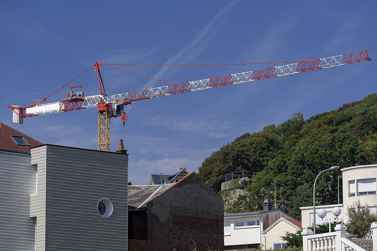 A tower crane in service
Image: Potain K5 50C (Alexandre Prevot, CC BY-SA 4.0), Wikimedia Commons. Not a specific Kobelco, Tadano, or Liebherr model discussed in the text — a representative tower crane for reading the boom and counterweight layout.

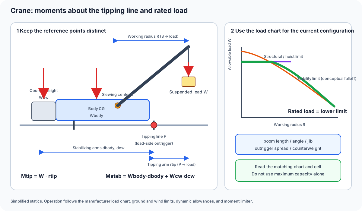
Figure 1 — Working radius R runs from the slewing center to the load, whereas the tipping-moment arm runs from the load-side tipping line to the load. Read rated load from the chart for the current boom, outrigger, and counterweight configuration as the lower of the structural and stability limits.
0. 30-Second Summary
- Cranes fall broadly into three categories: mobile cranes that can self-propel as road vehicles (rough-terrain cranes, all-terrain cranes, truck cranes, etc.), crawler cranes that self-propel on tracks, and tower cranes that are fixed to the ground and don't self-propel. Even under the law, "mobile crane" and "crane" (the fixed-installation category that includes tower cranes) are regulated as separate categories.
- The product of the suspended load W and working radius R creates the tipping moment M_{tip}=WR. A load can only be lifted within the range where the stabilizing moment M_{stab}, created by vehicle weight and counterweight, exceeds this. Japanese regulation requires the stability-limit load to be at least 1.27 times the rated load.
- A rated-load chart (load chart) is a table listing, for each combination of boom length, angle, and working radius, the smaller of the value set by the tipping moment and the value set by the structural strength of the boom itself or the hoisting mechanism.
- The overload-prevention device (moment limiter) is a safety device that calculates the tipping moment in real time from a load sensor and the boom's angle and length, sounding an alarm or automatically stopping the machine in a danger zone; it's legally mandated to be fitted.
- Kobelco's crawler cranes, Tadano's rough-terrain cranes, and Liebherr's mobile and tower cranes all let you confirm this mechanics as concrete figures in their published specs.
1. Splitting Cranes Into Three Types
A crane's mechanism and applicable job site change greatly depending on "what it rides on."
- Mobile cranes: Travel public roads on tires and work at the site. These include rough-terrain cranes, strong on rough, unimproved ground; all-terrain cranes, which can self-propel even on expressways; and truck cranes, mounted on a truck chassis. During work, outriggers are extended to widen the ground-contact footprint and resist the tipping moment.
- Crawler cranes: Self-propel on tracks. Ground pressure is low, suiting them to soft ground and to setting heavy items such as plant and wind-turbine foundations, but because they can't self-propel on public roads, transport requires disassembly and trailer transport. Many models use a lattice boom (truss structure), and the largest machines reach a rated total load in the hundreds-of-tonnes to thousand-tonne class.
- Tower cranes: Mount a jib on a tower-shaped structure fixed to the ground or to the building frame, extending upward as the building rises. Since they don't self-propel, they're not classified as "mobile cranes" under the law; rather than lifting capacity alone, the design centers on lifting capacity at each working radius, the jib's horizontal precision, and the procedure for disassembly and repositioning (climbing).
These three categories aren't mutually exclusive. Wheel cranes, for instance, sit somewhere between mobile and crawler cranes, and it's more practical to focus on "what it uses as a pivot, and how it resists the tipping moment" than on which category it falls into.
2. How to Read the Boom and the Rated-Load Chart
A crane's rated load is set for each combination of boom length l_b, boom angle \theta (the luffing angle from horizontal), and working radius R (the horizontal distance from the slewing center to the suspended load). Once boom angle and length are known, the working radius and boom-tip height can be approximated as
(where r_0,h_0 are the offset from the slewing center to the boom base). For the same boom length, the more the angle is laid down, the larger R becomes; the horizontal distance r_{tip} from the load-side tipping line to the load also grows, so the rated load falls.
Looking at a rated-load chart, in the region of small working radius, the load is roughly constant (capped by structural strength or wire-rope strength), while as the radius grows, it shifts to a region where the load falls off roughly as 1/R. The former is called the "strength limit" and the latter the "moment limit (stability limit)." The reason the rated load changes every time the operator changes the working radius is that whichever of these two limits is smaller is always the one applied. Configuration changes — adding a jib extension, raising an auxiliary jib, narrowing the outrigger spread — affect both limits, which is why the rated-load chart is prepared as a separate table for each combination of boom configuration, outrigger spread, and jib angle.
3. Tipping Moment and Stabilizing Moment
A crane tips over when, about the axis formed by the line connecting the outriggers' ground-contact points (the tipping line), the load-side moment exceeds the vehicle-side moment. Working radius R is measured from the slewing center, but the lever arm for tipping, r_{tip}, is the horizontal distance from the load-side tipping line to the load. In simplified statics, the suspended load W therefore produces
Against this, the stabilizing moment created by the vehicle's own weight W_{body} and counterweight W_{cw}, using their distances d_{body}, d_{cw} to the tipping fulcrum, is
The minimum condition for not tipping is M_{stab} \ge M_{tip}, but actual operation builds in a margin. Under the stability test based on Japan's mobile crane structural standards, the machine must not tip even when lifting a load equivalent to 1.27 times the rated load under the most unfavorable conditions — corresponding to a rule that sets the minimum ratio of stability-limit load to rated load at 1.27. This safety factor accounts for dynamic factors such as wire-rope stretch, wind, ground unevenness, and load swing.
Tadano's rough-terrain crane GR-1000EX-4 adopts a "Smart Counterweight" mechanism that can relocate the mounting position of the counterweight, and the company states this improves stability performance by up to roughly 22% versus the previous model. In terms of the equation, this is a design that gains M_{stab} by taking a larger d_{cw} (the counterweight's distance from the tipping fulcrum), meaning the rated-load chart can be raised even with the same counterweight mass.
4. Outrigger Reaction Force and Ground Pressure
Four individual outrigger reactions cannot be determined uniquely by equilibrium alone: frame, jack and ground stiffness and contact conditions matter. Consider only an idealized two-support-line model in one direction. For support-line spacing L and a combined vertical load W located x from the left support, static force and moment balance give
Assumptions are 0≤x≤L, vertical loading, a rigid body and both support lines in contact. These are total reactions on the support lines, not individual jack loads. Moving the load toward the tipping side unloads the opposite support toward zero. A stabilizing-moment margin is not the maximum loaded jack reaction. Actual setup uses manufacturer reaction data and load charts together with mat and ground conditions. Tadano reaction data.
5. The Overload-Prevention Device (Moment Limiter)
The moment limiter is a device that, using a load cell that detects hoist-wire tension and sensors for boom luffing angle and length, calculates the margin between the real-time tipping moment and the rated load. As it approaches the danger zone it sounds an intermittent alarm, and if the rated load risks being exceeded, it automatically stops dangerous-direction operations such as boom luffing, extension, or hoisting. In Japan, revisions to the mobile crane structural standards have made fitting an overload-prevention device mandatory, in addition to a load indicator.
Simplifying the control law, it compares the actual load moment M_{load}=W_{sensed}R(\theta,l_b) against the rated moment M_{rated} for the current boom configuration, giving a two-stage threshold:
This is the same idea as a hydraulic excavator's machine control restricting valve commands so as not to exceed the design surface — a design that connects the result of a mechanics-model calculation directly to a safety-side operating limit.
6. The Range of Cranes Seen in Current Products
| Maker / model | Classification | Key published specs | Characteristics |
|---|---|---|---|
| Kobelco SL16000J | Crawler crane (ultra-large) | Max rated total load 1,000 t × 5.4 m | Top-class model for heavy-item installation such as plant and wind-turbine foundations |
| Kobelco 7200G | Crawler crane (mid-to-large) | Max rated total load 200 t × 5.0 m | A core model used for general civil-engineering and construction lifting |
| Tadano GR-1000EX-4 | Rough-terrain crane | Max lifting capacity 100 t, class-longest 51 m boom | Improves stability performance by about 22% with Smart Counterweight |
| Liebherr LTM 1120-4.1 | All-terrain crane | Max lifting capacity 120 t, max lifting height 91 m, max working radius 64.0 m | A 4-axle machine combining public-road travel with high mobility on site |
| Liebherr EC-B series | Tower crane (flat-top) | Max lifting capacity 6–16 t, max jib length 58–78 m | A flat-top type with a lightened jib and head for improved transport/assembly ease |
A point to watch when comparing tables is that "max lifting capacity" is, in most cases, a single figure near the minimum working radius, and the rated load under actual site conditions (the required working radius, boom configuration, outrigger spread) is almost always smaller than that. Model selection should confirm the applicable cell of the rated-load chart at the working radius and lifting height actually needed on site — not just the single maximum figure.
7. Summary: A Crane Is Both "a Machine of Force" and "a Machine of Geometry"
A crane's capability can't be described by hydraulic or wire-rope strength alone. The basic premise of lifting is that the tipping moment created by boom angle and working radius must continuously be outweighed by the stabilizing moment created by vehicle weight, counterweight, and outrigger spread. The rated-load chart, the overload-prevention device, and the outrigger mats are all tools that make one single inequality — M_{stab}\ge M_{tip} (multiplied by a safety factor) — concrete for each site condition. Getting into the habit of reading not just the catalog's maximum lifting capacity, but at which working radius and boom configuration that figure holds, is the first step to safely selecting and operating a crane.
What changes when the same load is moved farther out?
Its overturning moment increases. Actual operation must use the rated load chart for the configuration and setup, not a simplified equation alone.
References
- Kobelco Construction Machinery — Crawler Crane SL16000J Main Specifications
- Kobelco Construction Machinery — Crawler Crane 7200G Main Specifications
- Tadano — Announcement of new rough-terrain crane for overseas markets (GR-1000EX-4)
- Liebherr — LTM 1120-4.1 Mobile crane
- Liebherr — Flat-top EC-B tower cranes
- Ministry of Health, Labour and Welfare — Structural standards for overload-prevention devices on cranes and mobile cranes
- Ministry of Health, Labour and Welfare — Revision of mobile crane structural standards (mandatory fitting of overload-prevention devices)
Current step · 5 / 7 · Construction Machinery Engineering
Comments
Please log in to post a comment
No comments yet.