Contents — find the section you need
If the computer resets when a motor starts, inspect the power path as well as software logs. Adequate nominal battery voltage does not guarantee adequate transient voltage at the converter or computer. This procedure concerns low-voltage DC mobile robots, not mains or high-voltage traction systems.
Draw the power path
Map the battery, protection, connectors, wiring, DC-DC converter and computer. Mark which sections carry both motor and computer current, including return conductors. Understanding batteries, actuators and DC-DC converters separately does not replace checking shared impedance.
Nominal voltage differs from loaded voltage
Assume total battery, wiring and contact resistance of 0.12 Ω and an extra 5 A during startup. The additional resistive drop is \Delta V=\Delta I R=0.6 V. This is an assumed example, not a measured newbot resistance. Wiring inductance and converter response add time-dependent effects.
Measuring only at the battery can miss downstream wiring losses. Check the actual model's minimum input voltage and supply conditions; Raspberry Pi documentation, for example, distinguishes model-specific requirements.
Locate the drop on one timeline
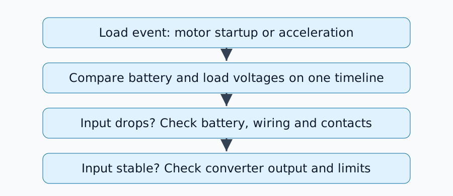
Fix the load event, battery charge, wiring and equipment versions. Observe battery terminals, converter input, converter output and computer terminals together where possible. An averaging multimeter display can miss short drops.
With an oscilloscope, verify probe ratings and grounding so the connection cannot short the circuit. Do not probe a circuit whose grounding you cannot establish; choose an appropriate differential measurement method. Keep measurements on the low-voltage DC side and do not defeat protection circuits.
Use observations to choose the next check
| Observation | Candidate causes | Next check |
|---|---|---|
| Battery voltage drops | Internal resistance, charge or current limits | Compare matching load conditions with specifications |
| Battery stable, converter input drops | Wiring or contacts | Voltage drop across each segment |
| Input stable, converter output drops | Current protection, transient response or input limits | Datasheet and load step |
| Converter output stable, computer input drops | Final cable or connector | Voltage at the load terminals |
The table narrows hypotheses; one waveform does not establish a unique cause. If supply voltage remains valid, investigate communication, reset signals, temperature and software.
A capacitor is not automatically the solution
Using the ideal discharge relation C=I\Delta t/\Delta V, supplying an extra 1 A for 10 ms within a 0.2 V drop requires C=0.05 F, or 50,000 µF. This assumes the capacitor supplies all missing current and is not a recommendation to install that value. ESR, inrush current and converter stability also matter.
Before adding components, check shared wiring resistance, contacts and converter operating limits. Use resources such as TI's power-management documentation to find the relevant component datasheet and transient specifications.
Repeat under matching conditions
Record the modification, minimum startup voltage, resets, trial count and battery state. One successful run is not a guarantee across charge states and simultaneous loads. The power issues in the newbot navigation record are possible applications of this measurement plan, but this article does not newly measure or establish their causes.
Comments
Please log in to post a comment
No comments yet.