Contents — find the section you need
Change parameters and verify
Open the panel, then press Run to load Python. You can stop execution and reset parameters. Results are computed on this device. No Python installation is required.
Local execution steps below are optional for reproducing the source results; they are not required for the browser experiment.
The experiment controls are in English.
Compare voltage drops in your browser
The panel above contains two independent arithmetic exercises, with synthetic curves and A/B comparison. No equipment or local Python installation is required. The original measurement procedure below remains optional; these curves do not diagnose a particular robot.
Supply path: an ideal source feeds battery resistance, then shared wiring/contact resistance, then an imposed total current. Shared resistance includes the outgoing and return paths. Battery-terminal voltage is Vs − I Rbattery; converter-input voltage is Vs − I (Rbattery + Rshared). The imposed current starts at 2 A, rises by the selected extra current at 0 ms, and returns at 100 ms. Repeated time coordinates show the left and right limits of the ideal steps. This is an algebraic resistance model, with no inductance, battery chemistry, charge state, current limiting or motor dynamics. Converter output, computer voltage and reset thresholds are not modeled. The current is prescribed, not calculated from a regulated constant-power load.
The defaults split the article's assumed 0.12 Ω into 0.04 Ω battery and 0.08 Ω shared resistance. An extra 5 A therefore adds 0.6 V of converter-input drop. Baseline resistance losses remain present: the 7 A plateau gives 11.72 V at the battery terminals and 11.16 V at the converter input from a 12 V ideal source. Move the resistance between the two segments while keeping the total fixed: the same downstream dip can have different battery-terminal evidence. This demonstrates measurement-point dependence, not a unique real fault diagnosis.
Separate capacitor exercise: a hypothetical capacitor alone supplies a constant missing current for the selected duration. Charge-related droop is I × t / C; terminal droop during discharge is I × ESR + I × t / C. Capacitance is entered in mF (50 mF = 0.05 F = 50,000 µF), time in ms. Time zero on this plot means just after discharge begins, so nonzero ESR gives an immediate drop. The plot stops just before the current ends: recharge and the end-of-discharge ESR recovery are not simulated. Initial capacitor voltage is unspecified; the graph shows voltage change, not a remaining supply voltage. It does not assert that any selected droop is physically usable with a particular starting voltage or load.
The default 1 A, 10 ms, 50 mF and zero ESR reproduce the article's ideal 0.2 V example. Halving capacitance doubles only the charge term; adding ESR adds its own step. The capacitor is not connected to the supply-path model. Changing capacitor settings cannot improve the upper curve. No converter-loop response, ESL, inrush, ripple rating, temperature, tolerance, stability or component recommendation is included. Slider bounds are teaching choices, not equipment ratings.
The data table includes both sides of supply steps and every capacitor sample. A/B uses common axes within each panel; the panels describe different experiments and time intervals. All outputs are synthetic calculations, not measurements or successful-start evidence. Use actual component documentation and the original measurement procedure for real fault isolation.
References: Analog Devices: real-source resistance model and TI: capacitance, ESR and transient behavior, reviewed 2026-09-20. This Lab applies Ohm's law and the constant-current capacitor relation under the assumptions above; it does not reproduce either source's hardware experiment or converter design. For energy sampling, see the separate power-measurement Lab.
모터 시동 시 컴퓨터가 재설정되는 경우, 전원 경로와 소프트웨어 로그를 점검하십시오. 배터리의 공칭 전압이 적절하다고 해서 컨버터나 컴퓨터의 과도 전압이 적절하다는 보장은 없습니다. 이 절차는 저전압 DC 이동 로봇에 관한 것이며, 주전원이나 고전압 구동 시스템에는 적용되지 않습니다.
전원 경로 그리기
배터리, 보호 장치, 커넥터, 배선, DC-DC 컨버터 및 컴퓨터의 배선도를 작성하십시오. 모터와 컴퓨터 전류가 모두 흐르는 부분(귀환 도체 포함)을 표시하십시오. 배터리, 액추에이터 및 DC-DC 컨버터를 각각 이해하는 것만으로는 공통 임피던스 점검을 대체할 수 없습니다.
공칭 전압과 부하 전압이 다른 경우
배터리, 배선 및 접촉 저항을 모두 0.12Ω으로 가정하고 시동 시 5A의 추가 전류가 흐른다고 가정하십시오. 추가 저항 강하는 \Delta V=\Delta I R=0.6 V입니다. 이는 가정된 예시이며, 특정 로봇에 대한 실제 측정 저항값이 아닙니다. 배선 인덕턴스와 컨버터 응답은 시간에 따라 변하는 영향을 더합니다.
배터리에서만 측정하면 하류 배선 손실을 놓칠 수 있습니다. 실제 모델의 최소 입력 전압과 공급 조건을 확인하십시오. 예를 들어, Raspberry Pi 문서에는 모델별 요구 사항이 명시되어 있습니다.
타임라인에서 전압 강하 위치 파악
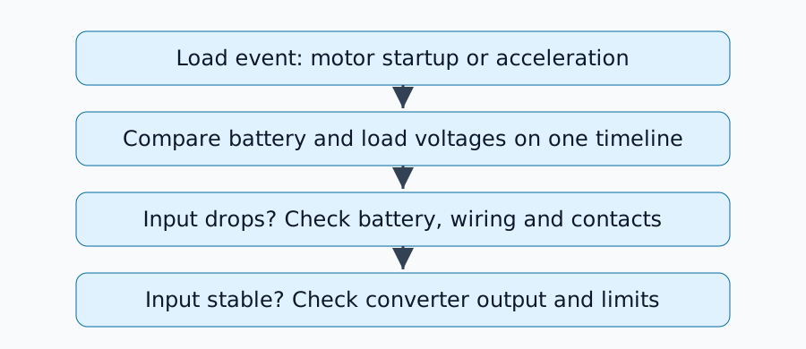
부하 이벤트, 배터리 충전량, 배선 및 장비 버전을 확인하십시오. 가능하면 배터리 단자, 컨버터 입력, 컨버터 출력 및 컴퓨터 단자를 동시에 관찰하십시오. 멀티미터의 평균값 표시 방식은 단락으로 인한 전압 강하를 놓칠 수 있습니다.
오실로스코프를 사용하여 프로브 정격과 접지 상태를 확인하여 회로 단락을 방지하십시오. 접지를 확인할 수 없는 회로는 프로브로 측정하지 마십시오. 적절한 차동 측정 방법을 선택하십시오. 저전압 DC 측에서 측정을 수행하고 보호 회로를 비활성화하지 마십시오.
관찰 결과를 바탕으로 다음 점검 항목을 선택하십시오.
| 관찰 결과 | 원인 가능성 | 다음 점검 항목 |
|---|---|---|
| 배터리 전압 강하 | 내부 저항, 충전 또는 전류 제한 | 사양에 맞는 부하 조건 비교 |
| 배터리 안정, 컨버터 입력 전압 강하 | 배선 또는 접점 | 각 세그먼트의 전압 강하 |
| 입력 안정, 컨버터 출력 전압 강하 | 전류 보호, 과도 응답 또는 입력 제한 | 데이터시트 및 부하 스텝 |
| 컨버터 출력 안정, 컴퓨터 입력 전압 강하 | 최종 케이블 또는 커넥터 | 부하 단자 전압 |
이 표는 가설을 좁히는 데 도움이 되지만, 하나의 파형만으로는 정확한 원인을 규명할 수 없습니다. 공급 전압이 정상 범위 내에 유지되면 통신, 리셋 신호, 온도 및 소프트웨어 문제를 조사하십시오.
커패시터가 무조건 해결책은 아닙니다
이상적인 방전 관계(C=I\Delta t/\Delta V)를 사용하여 0.2V 전압 강하 내에서 10ms 동안 1A의 추가 전류를 공급하려면 C=0.05 F, 즉 50,000µF의 커패시터가 필요합니다. 이는 커패시터가 부족한 전류를 모두 공급한다는 가정 하에 계산된 값이며, 해당 값을 설치하라는 권장 사항은 아닙니다. ESR, 돌입 전류 및 컨버터 안정성 또한 중요합니다.
부품을 추가하기 전에 공용 배선 저항, 접점 및 컨버터 작동 한계를 확인하십시오. 관련 부품 데이터시트 및 과도 응답 사양을 찾으려면 TI의 전력 관리 문서와 같은 자료를 활용하십시오.
동일한 조건에서 반복하십시오
수정 사항, 최소 시동 전압, 재설정 횟수, 시도 횟수 및 배터리 상태를 기록하십시오. 한 번의 성공적인 실행이 모든 충전 상태 및 동시 부하에서 성공을 보장하는 것은 아닙니다.
간헐적인 재설정으로 인해 성공적인 시작이 가려지지 않도록 각 시도마다 한 행씩 기록하십시오. 동일한 시동 간격 동안의 최소 전압을 기록하십시오. 각 채널을 별도의 실험에서 측정한 경우, 동시 파형이 아닌 개별 측정값으로 표시하십시오.
| 실험/변경 | 배터리 상태/동시 부하 | 배터리 최소값(V) | 컨버터 입력/출력 최소값(V) | 컴퓨터 최소값(V) | 재설정/관찰 |
|---|---|---|---|---|---|
| 변경 전/실험 1 | 기록 조건 | 측정값 | 측정값들 | 측정값 | 예/아니오; 시간 |
| 변경 후/실험 1 | 위의 조건과 일치 | 측정값 | 측정값들 | 측정값 | 예/아니오; 시간 |
측정 지점, 장비 설정 및 파형 파일을 표와 함께 보관하십시오. 전압 제한은 실제 장비 설명서를 참조하여 판단하십시오. 이 빈칸은 실험 결과가 아닌 기록 템플릿입니다.
댓글
먼저 로그인해 주세요.
아직 데이터가 없습니다.