Contents — find the section you need
Background and reading guide
Background Voltage, current, power, energy and unit conversion.
Fundamentals · Includes code examples.
Look up at a transmission tower and electricity seems to flow one-way from power plant to home. In reality, substations are constantly monitoring voltage, phase, and fault current, isolating only the section that needs it while keeping generation and consumption balanced at the very same instant. A substation isn't "a box that changes voltage" — it's a network node that safely reconfigures the flow of power.
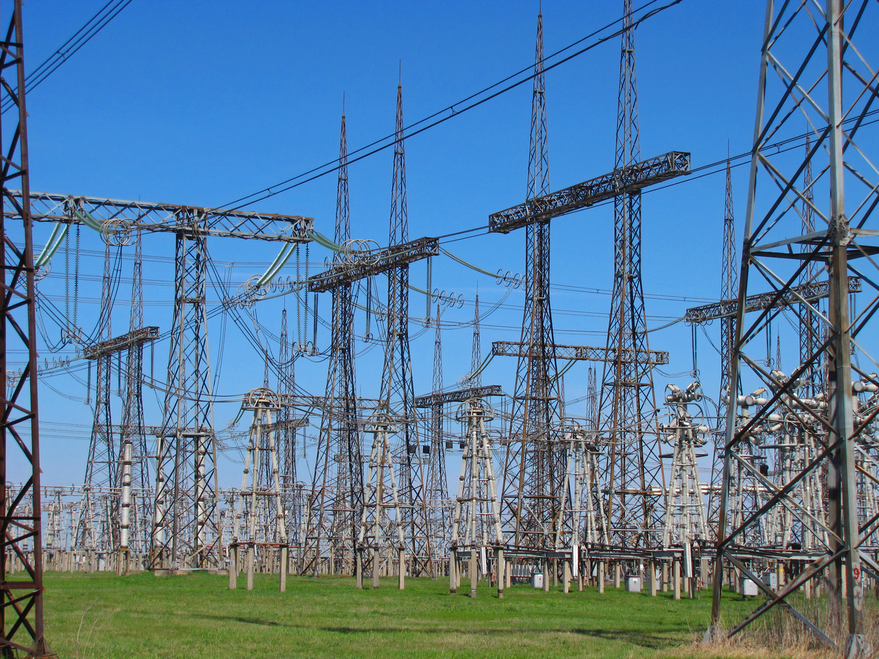 Extra-high-voltage switchyard
Image: Switchyard of electric substation 750kV (Novoklimov, CC BY 4.0), Wikimedia Commons. A representative switchyard, not a claim about a particular Japanese substation.

The 30-second version
- To send the same active power P, raising voltage V lowers current I=P/(\sqrt{3}V\cos\phi), which shrinks the transmission line's copper loss I^2R.
- A transformer exchanges voltage and current without changing frequency. Step-up transformers at power plants and step-down transformers near demand divide the grid into multiple voltage tiers.
- Circuit breakers cut fault current in milliseconds; disconnectors isolate equipment only once current is zero. Poor protection-relay settings mean the fault spreads too far, or unaffected equipment gets shut down unnecessarily.
- AC transmission (HVAC) fits well with the existing synchronous grid. For long distances, submarine cables, and asynchronous interconnections, HVDC using power converters becomes advantageous.
- Digital substations share current and voltage as sampled values over fiber optics. Cybersecurity and time synchronization become just as important as traditional insulation design.
1. A substation is the power grid's "intersection"
Between a power plant and a customer, there's typically a hierarchy of voltage tiers like this (values vary by country and grid):
Generator  11–30 kV
   │ Step-up transformer
Trunk transmission  154–500 kV ───── Long-distance transmission line ─────
   │ Transmission substation (switching, protection, reactive-power compensation)
Regional grid  66–154 kV
   │ Distribution substation
Distribution line    6.6–22 kV
   │ Pole-mounted transformer / service equipment
Customer    100/200 V, 400 V, factory high-voltage service
A substation houses busbars that hand power off, circuit breakers and disconnectors that switch circuits, instrument transformers that measure voltage and current, surge arresters that shunt lightning surges, protection relays that judge faults, and control/communication equipment. Because power flow can be switched to a different transmission line, or a maintenance section can be de-energized alone, grid reliability varies with substation configuration even when generation capacity is the same.
Figure 1 — A substation as seen through a single-line diagram. Three-phase conductors are drawn as a single line, with fault detection (relay) and circuit breakers placed on each circuit.
2. Why send power at high voltage?
For three-phase AC sending active power P, line-to-line voltage V_{LL}, line current I, and power factor \cos\phi are related by
which gives
For example, with power factor 1, resistance R=0.2\ \Omega per phase, and 100 MW being sent: at 66 kV current is about 875 A, at 275 kV about 210 A. Because resistive loss scales with the square of current, the idealized calculation gives roughly a seventeen-fold reduction. In practice, corona discharge, insulation clearance, transformer loss, and tower mechanical loading set the upper limit on voltage.
Raising voltage doesn't increase power itself. The essence is that raising voltage lets you lower current, increasing how much power the same transmission line can carry up to its thermal limit. The reason transformers keep being used with AC transmission is that electromagnetic induction lets this voltage exchange happen at high efficiency.
3. Reading a transformer as a "flux gearbox"
For an ideal transformer, turns ratio N_1:N_2 and voltage ratio relate as
Applying AC voltage generates flux \Phi in the core, inducing a voltage of the same frequency in the secondary winding. With DC, the flux saturates in one direction, so an ordinary transformer can't convert DC voltage directly.
Large-capacity transformers are designed around copper loss (winding resistance), iron loss (hysteresis and eddy-current loss), leakage reactance, and cooling capacity. Oil-filled transformers circulate insulating oil to carry heat to the radiator, and dissolved gas analysis (DGA) monitors signs of overheating or discharge. An on-load tap changer (OLTC) changes the turns ratio without interrupting load, keeping distribution voltage steady.
A transformer's short-circuit impedance suppresses fault current but increases the voltage drop during normal operation. Increasing transformer capacity reduces loss but raises fault current, which can exceed the circuit breaker's rating. The practical difficulty is that you can't optimize a piece of equipment in isolation — you have to decide it together with the grid's short-circuit capacity and protection coordination.
4. How circuit breakers, disconnectors, and busbars divide the work
Circuit breakers (CB)
A circuit breaker safely interrupts not just normal current but fault current. At high voltage, simply opening the contacts doesn't extinguish the arc, so arc-quenching media — SF_6 gas, vacuum, air — combine with fast-acting operating mechanisms. Development is currently moving toward reducing SF_6 for environmental reasons, with vacuum circuit breakers and alternative gas mixtures.
Disconnectors (DS)
A disconnector creates a visibly confirmed isolation gap, putting equipment into a state maintenance staff can safely work on. It has no capability to interrupt load current, so a circuit breaker must always cut current first. Interlocks are the last layer of safety against operating in the wrong sequence.
Busbars and switching configurations
A single bus is cheap, but a bus fault de-energizes every circuit. Double bus, bus-tie breakers, the breaker-and-a-half scheme, and GIS (gas-insulated switchgear) are all chosen by trading off equipment cost, footprint, maintainability, and fault impact. In urban areas, GIS — which encloses equipment in insulating gas — is favorable for saving space; in suburban outdoor substations, air-insulated AIS is easier to maintain.
5. Protection relays as "an algorithm that finds faults"
A protection relay receives current and voltage from CTs (current transformers) and VTs/PTs (voltage transformers) and estimates the type and location of a fault. Representative elements include:
| Protection element | What it watches | Best-suited faults | Caveats |
|---|---|---|---|
| Overcurrent (OC) | Current magnitude | Distribution-line short circuits/overload | Current is smaller for far-end faults |
| Ground fault (EF) | Zero-sequence current/voltage | Leakage to ground | Depends on grounding scheme and zero-sequence CT |
| Distance (21) | Apparent impedance V/I | Transmission-line fault location | Affected by power flow and series compensation |
| Differential (87) | Difference between terminal currents | Internal transformer/bus faults | Watch for CT saturation, communication delay |
| Frequency/ROCOF | f, df/dt | Grid separation, sudden supply-demand change | Waveform changes with inverter interconnection |
A transmission line's distance relay measures the impedance to the fault point as
Since line impedance is roughly proportional to distance, the breaker operates when Z_{app} falls inside a configured zone. But the design has to avoid misjudging "load encroachment," where load impedance under heavy power flow intrudes into the protection zone, and the impedance shift caused by series capacitors.
The time from fault detection to breaker opening is the sum of relay computation, communication, and the breaker's mechanical operation. Fast protection targets tens of milliseconds, though a deliberate time delay is sometimes set for selective tripping coordination with downstream systems. Reliability isn't just about speed — it's about "selectivity," leaving healthy circuits intact.
6. The electrical and mechanical sides of a transmission line
A transmission line is a distributed circuit with resistance R, inductance L, capacitance C, and leakage conductance G. A short line can be approximated with series impedance, but at a few hundred km you need to consider traveling waves and reflections, and the rise in receiving-end voltage known as the Ferranti effect — where, under light load, the line's capacitance supplies reactive power and receiving-end voltage exceeds sending-end voltage.
A simplified expression for deliverable transmission power is
set by the generator-side voltage E, the receiving-side voltage V, line reactance X, and the power angle \delta between the two ends. As power flow grows, \delta grows too, approaching the synchronous-stability limit. Beyond adding transmission lines, series compensation, STATCOM, synchronous condensers, and HVDC power-flow control can all create margin.
On the mechanical side, conductor sag, wind and ice loading, thermal elongation, and tower ground-bearing capacity all need to be satisfied simultaneously. As conductor temperature rises, sag increases and ground clearance shrinks, so Dynamic Line Rating (DLR) — calculating allowable current dynamically from weather data — is increasingly in practical use. The idea is to measure temperature, wind speed, and vibration with sensors and update transmission capacity on the safe side.
7. HVAC or HVDC — which to choose
HVAC (High-Voltage AC)
AC can have its voltage changed easily with a transformer and connects readily to the existing synchronous grid. Because multiple generators and loads synchronize at the same frequency, they also share inertia during a fault. On the other hand, reactive power and stability limit long distances, and charging current limits submarine cables.
HVDC (High-Voltage DC)
HVDC converts AC to DC via a converter, then back to AC at the sending and receiving ends. DC has smaller skin-effect and reactive-power issues, and beyond a certain distance it becomes advantageous for loss on long overhead lines and submarine cables. It also works for connecting grids of different frequencies, or for asynchronous interconnection that transfers power without tying two grids to the same synchronism.
Conventional LCC (thyristor-based) handles large power at high efficiency but requires reactive power on the AC side and faces constraints on weak grids. VSC (voltage-source converters using self-commutated devices like IGBTs) controls reactive and active power independently and is easier to apply to offshore wind and multi-terminal DC networks. Challenges include converter cost, DC circuit breakers fast enough to interrupt DC fault current, and control interaction.
8. Digital substations and cybersecurity
In digital substations based on IEC 61850, merging units sample CT/PT analog signals and distribute them as Sampled Values (SV) over a fiber-optic network. Switchgear status and trip signals are shared via GOOSE messages. Reducing copper wiring lightens the wiring load and makes it easier to reconfigure protection logic in software.
The flip side is that network faults and time drift directly affect protection operation. It takes combining time synchronization such as IEEE 1588 PTP, redundant rings, authenticated communication, configuration-file change management, and whitelist-based endpoint protection. Digitalization isn't just "adding IT" — it's a design change that broadens the failure mode from electromagnetic noise to packet delay and spoofing.
9. Where current technology and research stand
- SF_6 alternative switchgear: reducing greenhouse gas using vacuum circuit breakers, dry air, and CO_2 gas mixtures. Evaluated on interruption performance, lifespan, leak detection, and compatibility with existing equipment.
- Grid-forming converters: inverters for solar, batteries, and offshore wind behaving as voltage sources, supporting frequency and voltage on grids with fewer synchronous machines.
- Digital twins: integrating transformer thermal models, dissolved gas, breaker operation counts, and transmission-line weather data to estimate remaining life.
- Resilient protection: assuming GPS jamming or communication loss, duplicating adaptive protection that operates safely on local measurement alone alongside supplementary protection using wide-area measurement.
- Superconducting and high-temperature conductors: potential to increase transmission capacity within the same right-of-way, but cooling equipment and energy release during a fault remain barriers to practical use.
When reading research figures, it helps to check not just conversion efficiency but protection operating time, short-circuit behavior, maintenance cycle, and fail-safe behavior during a communication outage. Substations are infrastructure used for decades, so today's test results need to be evaluated with future component supply and standard revisions in mind.
Conclusion: a substation reveals the grid's design philosophy
The basics of transmission are reducing current and loss through higher voltage, but real-world reliability is set by a substation's switching configuration, protection-relay selectivity, transmission-line stability, and communication and maintenance design. HVAC and HVDC, AIS and GIS, single bus and double bus — each has reasons rooted in siting, cost, and fault impact.
When examining equipment, it helps to check these four things in order:
- What voltage tier, and which direction of power flow, does this equipment handle?
- During a fault, what does it measure, in how many ms, and which circuit does it isolate?
- Which is the bottleneck — reactive power, short-circuit capacity, or power angle?
- How is it prepared for communication loss, cyberattack, extreme weather, and component degradation?
With this perspective, you can read past a transformer's nameplate or a tower's voltage rating and into the design intent of a grid built to accept renewables and batteries.
Why transmit the same power at a higher voltage?
With other conditions unchanged, lower current reduces resistive loss. Insulation and equipment requirements increase in exchange.
References
- Organization for Cross-regional Coordination of Transmission Operators, Japan (OCCTO) (Japanese)
- Agency for Natural Resources and Energy — Transmission/Distribution and the Grid (Japanese)
- IEC 61850 — Communication networks and systems for power utility automation
- CIGRE — International Council on Large Electric Systems
- IEEE Power & Energy Society
- NREL — Grid Modernization
Current step · 9 / 15 · Power Engineering Primer
Comments
Please log in to post a comment
No comments yet.