Contents — find the section you need
Background and reading guide
Background Voltage, current, power, energy and unit conversion.
Fundamentals · Explanations of principles, structure and trade-offs.
Hydroelectric power isn't just about damming a river and building a big reservoir. A plant that channels water from a mountain intake through a long waterway, a small-hydro plant using water already released from an existing dam, and a pumped-storage plant that shuttles water between two reservoirs are all connected by one thing: extracting the potential energy of water. Water doesn't burn like a fuel. But the natural and civil-engineering system of rain, snow, watershed, and reservoir determines how much water there is, and valves, turbines, generators, transmission lines, and control rooms convert that energy into power at the exact moment it's needed.
Hydro's value can't be measured by annual generation alone. Equipment that can store water can raise and lower output relatively quickly, holding frequency steady, absorbing sudden swings in solar output, and even serving as a black-start power source during an outage. At the same time, seasonal rainfall patterns, safe flood-season spillway operation, sediment, fish migration, scenery, and downstream flow are constraints that maximizing generation alone can't resolve. This piece works through, in order, what happens in front of a turbine's blades, all the way to what pumped storage contributes to a grid heavy with renewables.
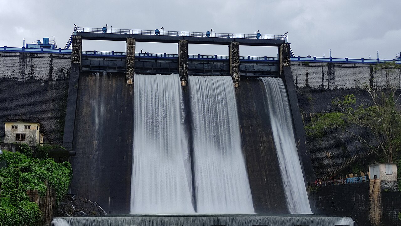 Dam-based hydro example
Image: Peechi Dam 3 (Lijovklm, CC BY-SA 4.0), Wikimedia Commons. A reservoir and dam landscape, not a complete view of the generating equipment.

0. The 30-second version
- Hydro output is set roughly by P=\rho g Q H\eta — the product of head H (effective drop), flow rate Q, and the combined turbine-to-generator efficiency \eta. Whether a plant relies on drop or on volume shapes what the equipment looks like.
- For high head and small flow, the Pelton turbine strikes buckets with a jet; the Francis turbine is the go-to for medium head; the Kaplan turbine, with adjustable propeller blades, handles low head and large flow. Turbines are chosen not just for peak efficiency but for the seasonal flow range, cavitation, and maintainability.
- Dam-type plants shift generation in time via storage; run-of-river plants generate along with river flow; pumped-storage plants send water back up to the upper reservoir with surplus power. Pumped storage is both a power plant and a large-scale, long-duration energy store.
- Generator rotational speed is tied to grid frequency. The governor moves guide vanes or a needle to change mechanical input, tracking supply-demand gaps over seconds to minutes — but it can't change abruptly, to avoid water hammer and vibration in the waterway.
- Hydro is renewable but still has environmental impact. Fish passages, intake screens, environmental flow, sediment management, and temperature/dissolved-oxygen monitoring need to be treated as design objects on par with the generation plan.
- Recent research themes include digital twins linking sensor data to physical models, degradation prediction, variable-speed pumped storage, and predictive control — all aimed at safely drawing more flexibility out of existing equipment.
1. Converting water's potential energy to output
Drop a mass m of water by height H and you get gravitational potential energy m g H. A plant doesn't think in terms of a single batch of water dropped at once — it thinks in terms of volumetric flow rate Q per second. With water density \rho, gravitational acceleration g, and combined efficiency \eta, the approximate electrical output is
For fresh water, \rho\simeq1{,}000\ \mathrm{kg/m^3} and g\simeq9.81\ \mathrm{m/s^2}. For example, with an effective head of 100 m, flow of 20 \mathrm{m^3/s}, and combined efficiency of 0.90, P\simeq17.7 MW. The effective head here isn't simply the raw water-surface difference between the upper and lower reservoirs — it's the drop that actually reaches the runner, after subtracting friction losses along the intake, sand-settling basin, waterway, pressure tunnel, and penstock, plus local losses at bends, valves, and inlets/outlets.
Writing the waterway loss as h_f and the gross head as H_g:
Here L is pipe length, D pipe diameter, v mean flow velocity, f the friction coefficient, and K the local loss coefficient. Increasing flow at first glance seems to raise output in proportion to Q, but loss grows roughly with v^2 — close to the square of flow rate. That's part of why, on a heavy-rain day, "just pass through as much as you can" isn't the right approach.
Figure 1 — Hydro turns head and flow into shaft power at the turbine, then sends it to the grid via the generator and transformer. Waterway losses, downstream water level, and intake constraints all factor into the real output.
Efficiency \eta isn't a single number either. It's the product of the turbine's hydraulic efficiency, the runner-and-bearing mechanical efficiency, generator efficiency, and transformer loss — and these differ near rated load versus at partial load. If leaves or sediment accumulate in the waterway, losses grow; if the guide vanes are throttled too far, the flow angle no longer matches the runner and efficiency drops. So what operators and controllers optimize isn't simply gate opening — it's a joint problem spanning reservoir storage, inflow forecasts, downstream release requirements, the efficiency curve, and the output the grid is asking for.
2. Three turbines chosen by head and flow
Turbines split broadly into impulse and reaction types based on how they apply water to the runner. Impulse turbines convert pressure to velocity through a nozzle and strike the jet against buckets in open air. Reaction turbines also use the pressure change of water filling a casing and draft tube to spin the runner. Neither is inherently better — they simply cover different maps of usable head and flow.
| Turbine | Best conditions | How it takes water | Regulation mechanism | Caveats / typical use |
|---|---|---|---|---|
| Pelton | High head, relatively small flow | Impulse — one or more high-speed jets nearly reversed by buckets | Needle, deflector, multiple nozzles | Long penstocks in mountainous terrain; watch for jet erosion and sand-driven bucket damage |
| Francis | Medium head, medium flow | Reaction — enters radially from a spiral casing, exits axially | Adjustable guide vanes | Most widely used; evaluate part-load pressure pulsation and cavitation |
| Kaplan | Low head, large flow | Reaction — propeller-shaped runner, axial flow | Dual control of guide vanes and variable-pitch blades | Rivers and low-tidal-range sites; complex hub, debris, and fish protection are all important |
Pelton turbine: turning pressure into a single fast jet
The Pelton turbine converts high head into velocity. Approximating nozzle exit velocity without losses gives v_j\simeq\sqrt{2gH} — for example, about 89 m/s at a head of 400 m. A splitter at the center of each bucket splits the jet in two and turns it back almost the opposite direction along a smooth inner surface. Because the water's momentum changes substantially, torque results on the runner. Throttling the jet with the needle adjusts flow, and during a sudden load rejection a deflector temporarily diverts the jet away from the buckets while the needle closes, holding water hammer down.
The Pelton turbine's strength is that the runner spins in a space close to atmospheric pressure, avoiding the draft-tube-side cavitation that tends to plague reaction turbines. But sand-laden water erodes buckets at high speed — sand-settling basins at the intake, wear-resistant surfaces, and periodic weld-overlay repair are all part of generation performance.
Francis turbine: the broadly applicable standard
The Francis turbine distributes water evenly around the runner via a spiral casing, with guide vanes shaping flow rate and inflow angle. Water enters radially and exits axially through the blade passages. It suits medium head and flow and is used in most storage and regulating-pond plants. It has a wider operating range than a fixed-blade propeller, but moving away from the design point tends to increase swirl at the runner exit, pressure pulsation, and vibration.
Cavitation deserves particular attention. When local pressure drops below water's vapor pressure, bubbles form, then collapse where pressure recovers. Repeated collapse damages blade surfaces and causes noise, vibration, and lower efficiency. Countermeasures include setting the runner appropriately low relative to the downstream water level, designing the draft tube and blade shape, avoiding prolonged operation in dangerous part-load bands, and measuring pressure and vibration.
Kaplan turbine: not letting large flow at low drop go to waste
The Kaplan turbine has a propeller-shaped runner resembling a ship's screw. At low head and large flow, even a small drop requires passing a large volume of water to get useful output. So it varies not just the guide vanes but also the pitch of the runner blades. Coordinating both, via a cam curve or control table, keeps the inflow angle to the blades close to optimal as flow changes, preserving part-load efficiency.
Movable blades are powerful but add hydraulic mechanisms, seals, and linkages inside the hub. Where a river carries a lot of driftwood, debris, ice, or fish, intake screens, debris removers, and a runner shape that considers passage all need to be examined together. You also can't assume low head automatically means low environmental impact — any structure crossing a river can affect both upstream and downstream migration.
Specific speed, used in turbine selection, is a dimensionless index combining rotational speed N, output P, and head H. One conventional notation is
though conventions and unit systems vary, so figures from different sources shouldn't be compared directly. In practice, decisions overlay candidate turbines' efficiency hill charts, cavitation margin, installation elevation, flow-duration curve, transport/installation constraints, and future operating points.
3. What separates dam-type, run-of-river, and pumped-storage plants
Dam-type plants with a reservoir
Dam-type plants temporarily store inflow in a reservoir and release it to match demand or water-use conditions. They can carry water forward anywhere from hours to a season, which is the big advantage — it decouples the instant rain falls from generation output. When a plant is multi-purpose — flood control, water supply, irrigation, river maintenance — generation doesn't get to use water freely on its own. Storage capacity has to be kept open during flood season, minimum releases maintained during drought, and generation releases arbitrated against downstream use.
Simplified, the reservoir storage balance S is
where Q_{in} is inflow, Q_{turbine} is turbine flow, Q_{spill} is spillway overflow, and Q_{release} is environmental/water-use release. Reservoir operation can be seen as an optimization problem adding rainfall forecasts and regulations to this equation. Maximizing generation alone risks eroding flood-season margin and downstream ecological flow.
Run-of-river and small hydro
Run-of-river plants don't rely on a large reservoir — they use the river's flow as it stands at that moment. A typical layout draws water from an intake weir into a waterway, settles sand in a settling basin, sends it from a headtank through a penstock to the powerhouse, and returns it downstream. Because it doesn't shift dam water levels much over the long term, it has less time-shifting freedom than a storage plant. But where the terrain works out, it can exploit head at existing agricultural waterways, erosion-control facilities, or pressure-reducing points on water-supply systems.
For run-of-river, the river-flow duration curve matters. Building larger equipment raises output during high-water periods, but the turbine sits idle during drought. Too small, and water that could be used even during average flow goes unused. Withdrawal amounts also come with permit conditions and maintenance flow requirements — water left for fish or the streambed shouldn't be treated as "surplus." Seasonal and hourly water temperature, turbidity, and intake-screen clogging all affect the real operating rate.
Pumped storage: large-scale energy storage that sends water back up
Pumped storage has an upper and lower reservoir; during hours when power is in surplus it pumps water from the lower to the upper reservoir, then runs it back down through the turbine when needed. Energy quantity is set by E\simeq\rho g V H\eta for water volume V and effective head H, letting it be sized in "power" and "capacity" as separate dimensions, much like a battery. Round-trip efficiency runs through the pump, turbine, motor/generator, piping, and transformer, so it isn't 100%. Even so, it holds large capacity for long durations, lasts a long time, and — where terrain and water rights allow — gives the grid substantial flexibility.
Thinking of pumped storage as simply "a device that pumps up at night and generates at midday" is inadequate today. Which hours have plentiful solar, strong overnight wind, congested transmission, or a need for reserve capacity varies day to day. Pumped storage's value spans not just wholesale electricity prices but frequency regulation, reserve capacity, avoiding renewable curtailment, black-start capability, and easing transmission congestion. In configurations where the rotating mass can be used like a synchronous condenser even while the pump is stopped, support for reactive power and short-circuit capacity also becomes a consideration.
4. Connecting the generator, governor, and grid frequency
A turbine shaft is usually directly coupled — or coupled through a gearbox — to a three-phase synchronous generator. For a synchronous machine with pole count p, the relationship between rotational speed n_s and grid frequency f is
500 rpm at 50 Hz with 12 poles, 600 rpm at 60 Hz with 12 poles. Hydro plants, matched to relatively slow, large-diameter turbines, sometimes use high-pole-count vertical-shaft machines. The automatic voltage regulator (AVR), which changes field current, mainly affects terminal voltage and reactive power, while the governor, which adjusts the water inlet, mainly concerns active power and rotational speed. Not conflating the two is the starting point for reading how the grid behaves.
If load suddenly increases, the electrical torque drawn from the generator temporarily exceeds turbine torque and speed drops. The governor, detecting the speed deviation, opens the guide vanes (for Francis/Kaplan) or the needle (for Pelton) to raise turbine input. The basic droop characteristic can be written as
where R is the speed regulation (droop), representing the slope of primary frequency response — raising output as frequency drops. Multiple plants on the same grid each share the shortfall according to their own droop. Secondary control then brings frequency and tie-line flow back to their reference values.
But water is not very compressible, and suddenly changing flow velocity in a long pipe sends a pressure wave through it. As a water-hammer approximation, the pressure rise from a change in flow velocity \Delta v is
where a is the pressure-wave speed, incorporating the elasticity of the water and pipe. Closing too abruptly puts a large strain on the penstock, valves, and casing, so surge tanks, pressure-regulating basins, relief valves, and appropriate governor time constants are all combined. What the electrical side wants — "respond faster" — can turn into dangerous pressure fluctuation on the waterway side. Only by understanding this tension can adjustable capacity be used safely.
Figure 2 — A hydro unit's governor changes water flow in response to frequency deviation, but the pressurized waterway has its own dynamics. The power grid and the hydraulic system can't be optimized separately.
Hydro can also be a candidate for black-starting a grid after a blackout. That role only materializes with a design that can start auxiliary equipment without external power, procedures for restoring communications and protection, and a plan for connecting loads in stages. Having water available isn't enough on its own — the operational plan needs to include a starting power source, control independence, training, and the reactive power generated when energizing transmission lines.
5. Putting existing equipment to work for renewable integration
As solar and wind grow, output variability isn't "something unpredictable" — it becomes an operational object accompanied by forecast error. The required regulating resource differs between minutes of variation from passing clouds, hours of ramp at sunset, and days of shifting wind conditions from a low-pressure system. Within its storage and flow capacity, hydro can offer governor response on short time scales, output allocation on medium time scales, and storage/pumped-storage scheduling on long time scales.
But "hydro is always flexible" is also the wrong assumption to make. Run-of-river plants are limited by flow rate; storage plants are limited by water rights, flood-season restrictions, and downstream release requirements. Older equipment may not be designed for frequent startup/shutdown or deep part-load operation. For renewable integration, beyond comparing rated MW, it's necessary to record up- and down-regulation headroom, response speed, sustainable duration, start time, minimum output, efficiency, and wear cost.
| Operational purpose | Typical time scale | Hydro's means | Design/operational considerations |
|---|---|---|---|
| Primary frequency regulation | Seconds to tens of seconds | Fine adjustment of guide vanes/needle via governor | Avoid water hammer, deadband, and vibration bands |
| Load following / reserve | Minutes to hours | Allocate reservoir release, start/stop units | Storage constraints, start time, part-load efficiency |
| Time-shifting solar/wind | Hours to days | Shift generation timing via pumped storage/reservoir | Round-trip efficiency, reservoir capacity, transmission congestion |
| Voltage/reactive power support | Instantaneous to minutes | Synchronous machine excitation, synchronous-condenser operation | Generator/transformer thermal limits, protection settings |
| Emergency restoration | Hours to days | Black start, forming islanded grids | Auxiliary power, communications, restoration procedures and training |
Variable-speed pumped storage is a technology that pairs power electronics with a conventional fixed-speed pump-turbine to allow rotational speed to change. In fixed-speed pumping, the power drawn from the grid is essentially set, so it struggles to track a middling amount of surplus renewable output. Variable speed lets pump input change continuously; quickly lowering pumping power when frequency drops provides support in the same direction as increasing generation output would.
At the same time, going variable-speed requires large-capacity frequency converters, cooling, insulation, protection coordination, and control software. Even where part-load efficiency improves, conversion losses and equipment cost need to be included in the evaluation. When upgrading equipment, it's important to confirm the rotational speed, torque, and pressure-fluctuation range that the existing waterway, runner, and motor-generator can tolerate, rather than deciding the electrical side first.
6. Environment and safety aren't add-on conditions
Hydro facilities can change a river's flow, sediment, temperature, and how organisms move. The magnitude of the impact isn't determined by whether there's a dam or not alone — it depends on the distance between intake and release points, the length of the dewatered reach, seasonal flow changes, weir height, screen mesh size, operating pattern, target fish species, and downstream use. Planning and refurbishment need to look at what happens outside the plant's boundary.
Fish passages provide a route for fish to migrate upstream. Types include pool-and-weir, Ice Harbor, and near-natural bypass channels, designed around the target species' swimming ability, body length, migration timing, water-level difference, and attraction flow. If the entrance sits too far from the main current, fish struggle to find it, and passage suffers if velocity is either too strong or too weak. Installing a fish passage and it actually functioning are two different things — verifying passage with video, tags, counts, and field observation is preferable.
For fish moving downstream, intake screens, bypasses, low-velocity intakes, and fish-conscious runner operation are all considered. Finer screen mesh reduces entrainment but increases clogging and head loss. Even a fish-friendly runner produces different results depending on species, body length, flow, and operating point. Environmental measures and generation efficiency aren't always in conflict, but the tradeoff needs to be handled with measurable indicators.
Environmental (maintenance) flow is water left in the dewatered reach after withdrawal to preserve the river's ecology, water quality, scenery, and use. Beyond a fixed minimum flow, some cases also account for spawning-season flow patterns, natural rise-and-fall rhythms, thermal stratification, dissolved oxygen, and streambed material movement. In reservoirs, sediment accumulation reduces usable capacity and changes sediment transport during floods. Sediment flushing, sediment bypass, and watershed erosion control affect both the plant's lifespan and the river environment.
On safety, dam monitoring, gate reliability, slopes, flood-time operation, and downstream warnings are the top priorities. Even as hydro automation advances, it has to be defined who operates on what basis during abnormal inflow, earthquakes, communication loss, sensor failure, or a cyberattack. Optimal control based on a single water-level gauge, however precise in normal times, doesn't qualify as safety design. It takes layering independent measurement, maintenance inspection, fail-safe gate behavior, and manual operating procedures.
7. Where digital twins and predictive maintenance stand today
A digital twin doesn't just mean reproducing a plant in 3D CG. It's the idea of linking measurements — water level, flow, pressure, vibration, temperature, gate opening, output — to physical models of reservoir balance, hydraulics, runner characteristics, generator, and controller, then using that for current-state estimation and future prediction. A good twin is judged not by how plausible its screen looks but by how precisely it can estimate unobserved quantities, how it detects model error, and how it improves operating decisions.
For example, time series of pressure pulsation and bearing vibration might allow early detection of operating bands prone to cavitation or runner abnormalities. Combining water level, rainfall, and inflow forecasts with market and supply-demand forecasts allows comparison of reservoir operation not just for the next day but weeks ahead. Using this in the field requires embedding physical constraints, missing-measurement handling, sensor calibration, and operator-interpretable rationale — rather than handing machine-learning predictions straight to control.
In research, the following points matter in particular.
- Quantifying degradation from flexible operation: measuring the fatigue that frequent startup/shutdown and part-load operation, done to track renewable variability, impose on the runner, bearings, guide vanes, and generator insulation.
- Fusing physics and data: building estimators that fill in losses and degradation that aren't fully understood using data, while never violating mass conservation, energy conservation, or equipment limits.
- Predictive control: updating output and pumping plans over hours to days using rainfall, inflow, price, and renewable forecasts, treating uncertainty as a range rather than a single-point forecast.
- Variable-speed machines' grid contribution: verifying how far converter control can support frequency and voltage, and how that aligns with protection during weak-grid conditions or faults.
- Integrating environmental monitoring: handling water temperature, turbidity, dissolved oxygen, fish passage, and sediment on the same time axis as operational data, not just flow.
This also calls for caution against overexpectation. More sensors don't necessarily get you closer to the truth — placement, calibration, communication latency, missing data, and data ownership all shape results. Rare floods or accidents leave little training data, and a model that's highly accurate in normal conditions can still fail at extrapolation. It's healthier to introduce digital twins as a way to give maintenance and operating decisions more to work with, not as a substitute for safety systems.
8. Practical checkpoints for reading a facility
When evaluating a hydro plant, rated capacity in MW alone doesn't tell you its character. Start by confirming gross head and effective head, design flow, the annual flow-duration curve, whether there's a reservoir, and how downstream water level changes. Next look at turbine type, the efficiency hill chart, the acceptable part-load band, cavitation margin, and start/stop time. Then check generator rating, AVR/governor, black-start capability, transformer and transmission-line capacity, and protection relay settings against grid conditions.
For pumped storage, confirm the usable capacity of the upper and lower reservoirs, head, generating and pumping output respectively, round-trip efficiency, minimum water level, the switching time from pumping to generating, and whether it's variable- or fixed-speed. On the environmental side, confirm intake/release locations, environmental flow, fish passage and screens, sediment, and downstream warnings. Only then does the question "how many MW can we use for renewables" turn into the practical question: "when, in which direction, for how long, and under which constraints can we use it."
9. Conclusion: using water means dealing with time and constraints
The hydro equation P=\rho g Q H\eta is simple, but behind its four symbols sit the watershed, reservoir, waterway, turbine, generator, transmission network, and river environment. The differences between Pelton, Francis, and Kaplan are differences in how they hand head and flow to blades. The differences between dam-type, run-of-river, and pumped-storage plants are differences in how far water can be shifted in time. And the governor and excitation system reconnect the power of water to the active power and voltage the grid needs.
On grids with a high renewable share, hydro is being reconsidered not as old, fixed equipment but as flexible infrastructure. That flexibility isn't unlimited, though. Water hammer, wear, storage, water rights, fish, sediment, and safety are constraints that need to be built directly into control, maintenance, and environmental monitoring. Digital twins and variable-speed pumped storage are tools that gradually push out this boundary — they don't replace physics and the field.
What happens to ideal hydro power if flow doubles at equal head?
It doubles at unchanged efficiency. Real waterways, operating limits, and water availability can invalidate the proportional assumption.
References (official and primary sources)
- Agency for Natural Resources and Energy — Hydroelectric Power (Japanese)
- Ministry of Land, Infrastructure, Transport and Tourism — Dam and River Management (Japanese)
- Organization for Cross-regional Coordination of Transmission Operators, Japan (OCCTO) — Grid and Supply-Demand Information (Japanese)
- International Energy Agency — Hydropower
- U.S. Department of Energy Water Power Technologies Office — Hydropower
- National Renewable Energy Laboratory — Hydropower
- U.S. Fish and Wildlife Service — Fish Passage
- International Hydropower Association — Pumped Storage
Current step · 4 / 15 · Power Engineering Primer
Comments
Please log in to post a comment
No comments yet.