Contents — find the section you need
Background and reading guide
Background Basic vectors, matrices and camera projection.
Fundamentals · Includes code examples.
Suppose an image taken with a camera has several known 3D points on a map that correspond to points in it. The problem of finding where the camera was placed and which way it was pointing is PnP (Perspective-n-Point). It's used in common across Visual SLAM map tracking, overlaying virtual objects in AR, hand-eye calibration for robots, and pose estimation for surveying cameras.
0. 30-Second Summary
- The input is the camera intrinsic matrix K, known 3D points \mathbf X_i, and their corresponding image points \mathbf u_i. The output is a rotation R and translation t.
- Minimize reprojection error under \mathbf u_i\sim K(R\mathbf X_i+t). Three-point P3P can return multiple poses; additional points help select a solution. Four points alone do not guarantee outlier detection; use more correspondences and RANSAC.
- EPnP expresses each point as a linear combination of 4 virtual control points, solving for many points quickly. A final nonlinear optimization such as Levenberg–Marquardt then refines the result.
- If outliers get mixed into the correspondences, the entire pose estimate can collapse, so it's verified with RANSAC-PnP, positive-depth checks, and frame-to-frame consistency.
- Estimates can become unstable when image points are concentrated in a small area, intrinsics are wrong, or rolling shutter or moving objects violate the model. Planar targets also have dedicated solvers such as IPPE.
1. The Projection Model
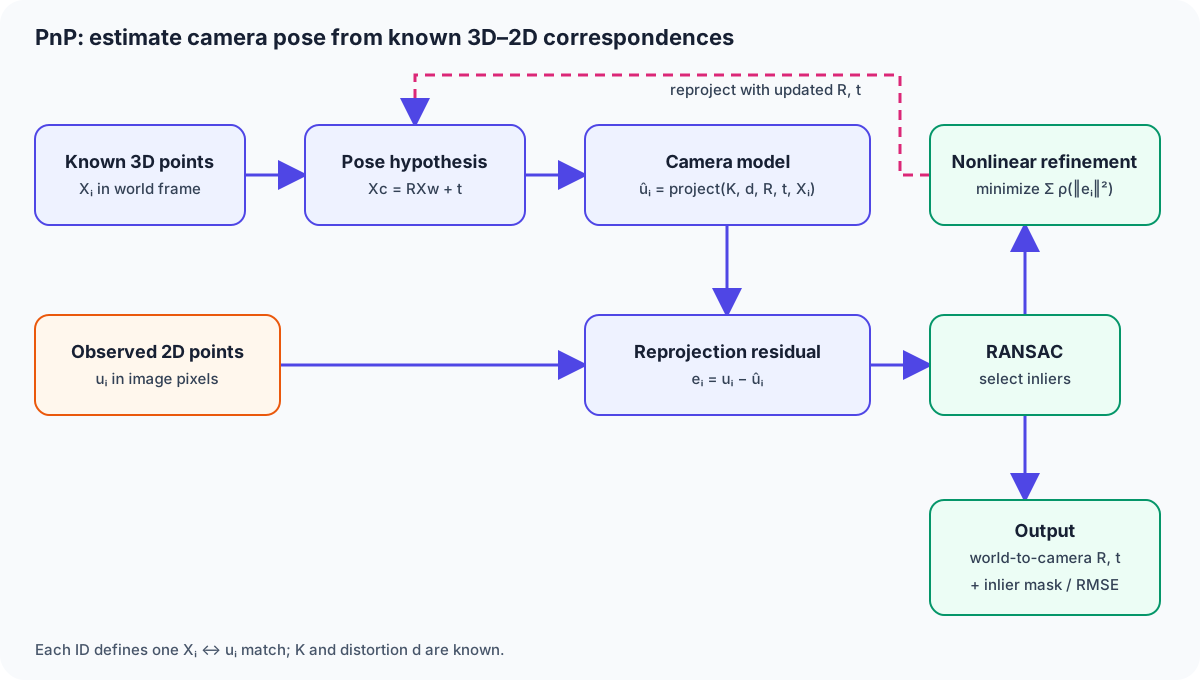
Figure 1 — Matching IDs define 3D–2D correspondences. PnP forms a pose hypothesis, rejects outliers by reprojection residual, and refines R,t, which map world coordinates into camera coordinates.
Let a point in the camera coordinate frame be \mathbf X_c=R\mathbf X_w+t. In the pinhole model, the normalized image coordinates are
and the pixel coordinates are obtained via the intrinsic matrix
as \mathbf u\sim K\mathbf X_c. R\in SO(3) is the rotation and t the translation. If there's lens distortion, distortion correction is needed before and after projection.
The unknowns are the 6 degrees of freedom of 3 rotational plus 3 translational. Given n correspondences between 3D points \mathbf X_i and observations \mathbf u_i, the reprojection error
is minimized. \pi is the perspective division and \rho is a robust loss such as Huber's.
Do not confuse the transform with the camera position
OpenCV's solvePnP returns rvec, tvec for the transform that maps object/world points into the camera frame. To obtain the camera center in world coordinates, use \mathbf C_w=-R^Tt; for a camera pose, invert T_{cw} to obtain T_{wc}. Treating tvec itself as the camera's world position is a common error. Also avoid applying distortion twice when the input image points have already been undistorted.
2. P3P, AP3P, and EPnP
P3P (Perspective-3-Point), which recovers the distance from the camera center using the image angles of 3 points and the distances between the 3D points, has up to 4 solutions. The correct one is selected by checking against a 4th point or against the map's known pose. AP3P is a fast variant that reorganizes the solution algebraically.
When there are many points, EPnP (Efficient PnP) expresses every 3D point as a weighted sum of 4 virtual control points.
The control points' camera coordinates are found from linear equations, and the rotation and translation are recovered from them. Because its computational cost is nearly linear in the number of points, it's well suited to building an initial pose from SLAM's many landmarks. After the initial solution, the reprojection error is refined iteratively with Levenberg–Marquardt.
3. RANSAC-PnP
Feature-point correspondences get mixed with similar-looking patterns, moving objects, and wrong map IDs. The standard approach is RANSAC: build a tentative pose from a minimal point set, reproject every correspondence, and count how many inliers fall within a threshold. The number of iterations N needed, given outlier rate \epsilon, minimal sample size s, and success probability p, is determined by
Since the required number of iterations grows sharply with the outlier rate, lower \epsilon beforehand using a feature-point ratio test, grid-based dispersion, or a dynamic-object mask. OpenCV's solvePnPRansac is used by explicitly specifying the point count, flags (EPNP, P3P, SQPNP, etc.), reprojection threshold, and confidence.
4. Spotting Degeneracy
Coplanar point sets
Planar points can support pose estimation; OpenCV provides IPPE specifically for this configuration. However, near-frontal views or distant targets can make competing poses difficult to distinguish under noise. A homography also describes the correspondences on a plane. Use a suitable solver and inspect candidate poses rather than treating every planar target as unsolvable.
Narrow image coverage and long range
PnP directly uses one image and known 3D points, so inter-frame parallax is not itself a required input. It is nevertheless poorly conditioned when correspondences occupy only a small image region, the target is distant and appears small, or the 3D points have little depth variation. Do not accept a result from its inlier count alone: inspect image coverage, reprojection RMSE, and pose covariance or sensitivity to perturbations, then fuse an IMU or depth sensor when needed.
Calibration and timing
Errors in focal length, principal point, and distortion turn into a systematic reprojection error across every point. A lens whose intrinsic matrix changes with zoom, temperature, or focus needs to be recalibrated. In vehicles and drones, if the row timing of a rolling shutter isn't synchronized with the IMU, PnP will return a "bent" camera pose.
5. The Role of PnP in Visual SLAM
In Visual SLAM, as the number of previously-triangulated map points grows, the camera pose can be tracked frame by frame with PnP. With the pose held fixed, new points are triangulated, and once enough keyframes have accumulated, Bundle Adjustment jointly optimizes the pose and the map. It's easiest to understand this as a division of labor: PnP is the lightweight front end, and Bundle Adjustment handles global consistency.
6. Implementation Checklist
- Calibrate K and the distortion with a checkerboard or similar, and record the reprojection error.
- Align the units (m/mm) and coordinate frame of the 3D points with the distortion-correction state of the image points.
- Narrow down correspondences with a ratio test, mutual nearest neighbors, and temporal tracking.
- Remove outliers with RANSAC-PnP, and save the inlier distribution and reprojection error.
- Check that depth is positive, that the pose change is physically plausible, and that the difference from the previous frame is reasonable.
- If conditions are poor, fall back to an IMU, depth, a homography, or reinitialization.
Minimal implementation sequence
With OpenCV, first obtain rvec, tvec, inliers from solvePnPRansac, pass only the inliers to solvePnPRefineLM, and finally use projectPoints to compute the inlier RMSE and error distribution yourself. A successful API return alone does not detect excessive mismatches, clustered points, or a physically impossible pose.
ok, rvec, tvec, inliers = cv2.solvePnPRansac(
    object_points, image_points, K, dist,
    flags=cv2.SOLVEPNP_EPNP,
    reprojectionError=3.0, confidence=0.999, iterationsCount=200,
)
if not ok or inliers is None or len(inliers) < 6:
    raise RuntimeError("PnP failed or has too few inliers")

idx = inliers.ravel()
rvec, tvec = cv2.solvePnPRefineLM(
    object_points[idx], image_points[idx], K, dist, rvec, tvec
)
projected, _ = cv2.projectPoints(object_points[idx], rvec, tvec, K, dist)
rmse = np.sqrt(np.mean(np.sum(
    (projected.reshape(-1, 2) - image_points[idx].reshape(-1, 2)) ** 2,
    axis=1,
)))
R, _ = cv2.Rodrigues(rvec)
camera_center_world = -R.T @ tvec.reshape(3, 1)
Neither 3.0 px nor six inliers is a universal acceptance threshold; they are only starting values for this example. Derive thresholds from image resolution, feature precision, and the application's allowed pose error. Also verify that the inliers are not clustered in one image corner and that every point has camera-frame depth Z_c>0.
A reproducible synthetic example: outliers versus wrong focal lengths
This is a synthetic calculation run by Duskcoil, not a measurement of a physical camera. Project 48 non-planar 3D points (metres) into a 1280×720 image, then add independent Gaussian noise with standard deviation 0.5 px to each image coordinate. In the outlier cases, replace 12 of those observations with random coordinates inside the image. The random seed is 20261001.
Ground truth uses f_x=f_y=800 px, principal point (640,360), and no distortion. The world-to-camera Rodrigues vector is (0.15,-0.10,0.05) rad and translation is (0.20,-0.10,5.0) m. Only the wrong-focal case changes the estimation focal lengths to 920 px, keeping the observations unchanged. EPnP initializes each pose. RANSAC uses a 3 px threshold, 200 iterations and confidence 0.999; LM refines the selected points. Without RANSAC, LM uses all 48 points.
| Condition | Points used for refinement | Fit RMSE (px) | Camera-centre error (m) |
|---|---|---|---|
| No outliers + RANSAC | 48 | 0.660 | 0.0036 |
| 12 outliers, no RANSAC | 48 | 185.826 | 1.9522 |
| 12 outliers + RANSAC | 36 | 0.673 | 0.0077 |
| Focal lengths 15% too large + RANSAC | 48 | 1.242 | 0.7456 |
RMSE is evaluated on the correspondences used for refinement. Camera-centre error is \|\hat C_w-C_w\|, measured against the known synthetic truth. The fitted point sets differ between rows, so do not rank the methods solely by these RMSE values.
With outliers and no RANSAC, the API still returned success and every estimated depth was positive, yet the camera centre was about 1.95 m from the truth. RANSAC retained 36 points and reduced the centre error to about 0.0077 m on this input. With focal lengths 15% too large, all 48 points were retained: an RMSE of about 1.24 px still accompanied a centre error of about 0.75 m. A low reprojection error or positive depth alone does not establish that the intrinsics are correct.
This uses one layout and one seed. Results depend on point distribution, range, noise and outlier rate. In real monocular images the true camera centre is usually unknown, so this error cannot be computed directly. Validate against independent calibration or reference poses and multiple conditions.
Run it yourself
Executable reproduce.py · Input points CSV · Full results JSON
Recorded environment: Python 3.12.3 / OpenCV 4.6.0 / NumPy 1.26.4. Save reproduce.py and run the command below in an environment with NumPy and OpenCV installed. The script generates the inputs from its fixed seed; the downloadable CSV is an exported reference, not an input file consumed by the script. Different OpenCV versions, builds or random-number implementations can change final digits or selected inliers. Keep the environment information in the output JSON.
python -m venv .venv
# Windows: .venv\Scripts\activate
# macOS / Linux: source .venv/bin/activate
python -m pip install numpy==1.26.4 opencv-python-headless==4.6.0.66
python reproduce.py --output results.json --inputs inputs.csv
7. Summary
PnP is the bridge that converts correspondences between a 3D map and a 2D image into a camera pose with 6 degrees of freedom. Build an initial solution with P3P/EPnP, remove outliers with RANSAC, and refine with nonlinear optimization. Only by managing point layout, calibration, image-point spread, and time synchronization together does this become a stable pose estimate for Visual SLAM or AR.
Does PnP only need two images?
Its basic inputs are known 3D points, their 2D image correspondences, and camera intrinsics. This differs from estimating motion from 2D-to-2D matches.
References
Current step · 11 / 19 · Computer Vision Primer
Comments
Please log in to post a comment
No comments yet.