Contents — find the section you need
Background and reading guide
Background Circuit voltage, current, resistance, inductors and capacitors.
Fundamentals · Explanations of principles, structure and trade-offs.
Converting the AC from a wall outlet into a battery's DC, converting that battery DC back into a motor's three-phase AC, matching a solar panel's voltage to the grid — power electronics handles all of these. Rather than dropping voltage by turning it into heat through a resistor, it switches semiconductor switches such as MOSFETs and IGBTs at high speed, temporarily storing energy in inductors and capacitors to synthesize the waveform that's needed.
 BLDC motor example
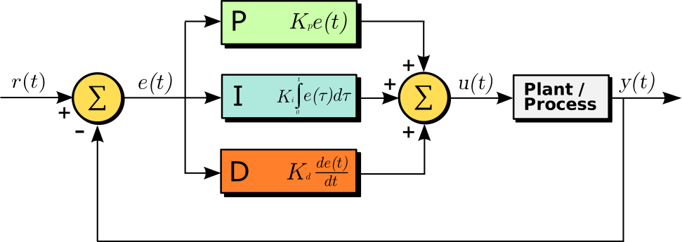 Control-loop example
Images: Outrunner (1sfoerster, CC BY-SA 3.0) / PID controller block diagram (Arturo Urquizo, CC BY-SA 3.0), Wikimedia Commons. Representative motor and controller examples.


0. 30-Second Summary
- A power semiconductor isn't a "component that amplifies power" — it's an electronic switch that chooses, at high speed, whether current flows or is blocked.
- If D is the fraction of a switching period T_s spent on, an ideal Buck converter gives V_o=D V_{in}. In a real device, conduction loss, switching loss, and losses in magnetic components all matter.
- An inverter slices DC into fine pieces with PWM, synthesizing a sine wave as the average. In a motor, voltage, frequency, and phase are varied to control torque and speed.
- SiC and GaN are materials that can target high voltage tolerance, high-speed switching, and high-temperature operation, but gate drive, parasitic inductance, EMI, and cost make the design harder.
- A power converter isn't a finished product on efficiency alone — thermal resistance, insulation, short-circuit protection, control software, grid standards, and maintainability all have to come together too.
1. Building an "Average Value" Through Switching
Place a switch S in series with a DC source V_{in}, and turn it on for DT_s out of every period T_s. If the load carries a sufficiently large inductor, the average voltage seen by the load is
Even though the switch itself only ever outputs 0 V or V_{in}, the inductor's current smooths out the transitions, and the capacitor's voltage holds the average value. That's the core intuition behind power electronics.
Diagram: Duskcoil. The switch's rectangular waveform is smoothed by L and C, delivering an average voltage to the load. Raising the switching frequency lets the passive components shrink, but increases losses and EMI.
2. Choosing Among Representative Topologies
Buck, Boost, Buck-Boost
Buck (step-down) is used to build, say, a 12 V rail from a battery; Boost (step-up) raises the low voltage of a solar cell or fuel cell to a high DC link; Buck-Boost converts to either above or below the input voltage. In the ideal continuous-conduction mode, the relationships are
As the duty cycle D approaches 1, the ideal Boost voltage goes to infinity, but in a real device, switch voltage rating, diode reverse recovery, inductor saturation, and control instability all impose limits well before that. At high voltage and high power, rather than a simple single-stage conversion, topologies such as interleaving, isolated LLC, or DAB (Dual Active Bridge) are chosen instead.
Rectifiers and power factor correction
Rectifying AC with a diode bridge, a capacitor-input supply draws a large pulse of current near the peak of the voltage waveform. Poor power factor increases the current the distribution equipment has to carry, so a Boost-type PFC (power factor correction) circuit is used to shape the input current closer to a sine wave. Data-center power supplies, EV fast chargers, and industrial inverters all need to satisfy efficiency and harmonic regulations at the same time.
Inverters and three-phase motors
A three-phase two-level inverter drives 6 switches (upper and lower) in a complementary pattern, synthesizing a three-phase voltage from the DC-link voltage. Turning the upper and lower switches on at the same time would short-circuit the DC bus, so a dead time of a few hundred ns to a few µs is inserted. Representative modulation schemes include sinusoidal PWM, which compares a reference sine wave against a triangular carrier to build the average voltage, and space-vector PWM (SVPWM), which injects a zero-sequence component across the three phases to raise DC-voltage utilization.
In a permanent-magnet synchronous motor, the q-axis current, perpendicular to the rotor flux, produces torque. A simplified torque equation is
where p is the number of pole pairs, \psi_f the permanent-magnet flux, and i_q the q-axis current. The current loop is controlled at a few kHz, and rotor angle is obtained either from a position sensor or via sensorless estimation. In an EV, the same inverter switches between high torque at low speed, field weakening at high speed, and regenerative braking.
3. Choosing Between Si, SiC, and GaN
Silicon MOSFETs/IGBTs are mature, and strong on cost and reliability. SiC MOSFETs suit high voltage tolerance, low loss, and high-temperature operation, and are increasingly adopted in EV main drive inverters, PCS units for solar and storage, and railway auxiliary power supplies. GaN HEMTs excel at high-speed switching and low gate charge, and are strong in areas where high frequency and small size pay off — hundred-volt-class AC adapters, server power supplies, wireless power transfer.
Switch losses broadly split into two kinds.
R_{on} is on-resistance, t_{on/off} the transition time, and f_s the switching frequency. Raising the frequency shrinks the magnetic components, but switching loss, gate-drive loss, and EMI all increase. Because SiC/GaN devices' parasitic wiring inductance turns into voltage overshoot more readily the faster they switch, the design has to account for package, layout, gate resistance, and snubbers all together.
4. Thermal Design, Insulation, and Protection Determine the Product
With junction temperature T_j, case temperature T_c, and thermal resistance R_{th,jc}, the steady-state approximation is
Including the cold plate, thermal grease, heat sink, and coolant flow rate, T_j has to be kept under its rated value in the worst case. In an EV inverter, coolant inlet temperature, short-term overload, heat from regeneration, and even salt water and vibration all affect lifetime.
In a high-voltage battery, creepage and clearance distances, insulation monitoring, pre-charge, fuses, contactors, and a discharge resistor are combined. Short-circuit protection isn't simply "the faster the better" — it needs time coordination that avoids halting operation on a false trigger while still cutting power reliably before the semiconductor is destroyed. Control-software watchdogs, dual current sensing, and functional-safety standards (ISO 26262, IEC 61508, etc.) are all designed in as part of the circuit too.
5. Where It's Used
| Field | Input | Conversion | Real value delivered |
|---|---|---|---|
| EV/rail | High-voltage battery, catenary | DC-DC, three-phase inverter, regeneration | Torque control, range, regenerated power |
| Solar/storage | PV, battery | MPPT, PCS, bidirectional DC-DC | Grid interconnection, peak shifting, reactive power |
| Data center | AC | PFC, isolated DC-DC, 48 V distribution | Efficiency, redundancy, power density |
| Robotics | AC/DC | Servo amplifier, DC link | Position/velocity/torque response |
| Industrial heating | AC | High-frequency inverter | Induction heating, temperature control |
| Home appliances | AC/DC | Inverter, converter | Energy savings, quiet operation, variable speed |
6. A Lens for Reading Current Research
Research isn't focused only on "making switches faster." Progress is happening simultaneously on SiC gate reliability and short-circuit withstand, GaN's dynamic on-resistance, thermal paths in 3D power modules, high-frequency loss in magnetic materials, predictive compensation in digital control, and EMI reduction for wide-bandgap devices. System-level research also matters — multi-phase interleaving that modularizes converters so operation continues even after a failure, V2G linking vehicles to the grid, DC distribution, and wireless power transfer.
When reading an efficiency graph in a paper, check not just the rated operating point but the load fraction, input voltage, cooling conditions, switching frequency, and measurement bandwidth. The same 99% figure represents 100 times more heat lost in a 1 MW inverter than in a 1 kW power supply. When choosing a product, it's better to prioritize the weighted-average efficiency over the actual load profile, lifetime, maintainability, and EMI test results, rather than peak efficiency alone.
7. Summary
Power electronics decomposes electrical power into "semiconductor on/off," "energy storage in magnetic components," "smoothing by capacitors," and "feedback in control software," and reassembles them into whatever voltage, current, and frequency is needed. Memorizing the Buck equation or PWM is only the entry point — the final performance is determined by the combination of loss, heat, insulation, EMI, protection, standards, and control-loop timing.
Is minimizing switch on-resistance sufficient?
Conduction and switching losses differ. Evaluate frequency, current, thermal behavior, control, and EMI at the intended operating conditions.
References
Current step · 1 / 5 · Power Electronics Primer
Comments
Please log in to post a comment
No comments yet.