Contents — find the section you need
Change parameters and verify
Open the panel, then press Run to load Python. You can stop execution and reset parameters. Results are computed on this device. No Python installation is required.
Local execution steps below are optional for reproducing the source results; they are not required for the browser experiment.
The experiment controls are in English.
Explore footprint geometry in your browser
Change the rectangular body dimensions, corridor width, heading and lateral offset in the panel above. The diagram and signed gaps describe an exact rectangle between two infinite parallel walls. No ROS or local Python is required. The diagnostic workflow below remains separate from this geometry exercise.
The rectangle centre is the supplied reference point. World x runs along the corridor, world y points across it, and positive heading rotates counterclockwise from +x. Length L lies along body x; width B lies along body y. Walls lie at y=±W/2 and the centre at (0,e). For heading θ, the transverse span is S=L|sin θ|+B|cos θ|. The upper-wall gap is W/2−e−S/2, the lower-wall gap is W/2+e−S/2, and the minimum is W/2−|e|−S/2. Positive means separation; zero means contact; negative means overlap with a wall half-plane. These are signed transverse gaps, not general polygon-distance or costmap outputs. The numerical contact label uses a tolerance of 10⁻¹² m, not an operating margin.
The default 0.60 m width in a 0.80 m corridor gives 0.10 m on each side at zero heading and offset. Try a 30° heading, a 0.10 m offset, a 90° heading, or a wider corridor. Changing heading can move a corner into a wall even when the aligned width fits. A/B uses equal x/y scales and a common extent across both results; the table lists all four transformed corners in metres.
The dashed circle has radius R=√(L²+B²)/2. It bounds all orientations during a full rotation about the fixed rectangle centre. The minimum gap over that full rotation is W/2−|e|−R, calculated analytically rather than from sampled angles. This is not the gap for a particular requested turn, a planned swept path or a kinematically feasible manoeuvre. A 90° pose can fit while intermediate orientations overlap. The rectangle dimensions describe the entire assumed outline; there is no additional footprint padding.
All inputs are synthetic teaching choices. There are no map cells, obstacle observations, inflation costs, localization uncertainty, payload model, TF, planner, controller, velocity commands or actual Nav2 execution. A positive geometric gap does not establish passage feasibility or operating safety. The full-turn circle is an explanatory envelope, not a proposed robot_radius configuration. Nav2's tuning guide distinguishes robot footprint choices from inflation potential fields; the inflation parameters describe costs that this exercise does not compute. References reviewed 2026-09-20.
For supplied map/pose/goal checks, use the separate navigation Lab. Continue below to inspect why a real navigation stack may stop.
보이는 경로가 현재 자세에서 실행 가능한 속도 명령이 존재한다는 것을 보장하지는 않습니다. 계획과 실행을 별도로 진단하십시오. 이 워크플로는 ROS 2/Nav2 Jazzy를 대상으로 하며 문서를 기준으로 검증되었습니다. 하드웨어 구동 보고서는 아닙니다.
정지 구간 캡처
전역 경로, 로컬/전역 코스트맵, 풋프린트, TF, 오도메트리, 속도 명령, 액션 결과 및 로그를 수집합니다. RViz에서 일정한 시간과 프레임의 데이터를 오버레이합니다. 시작 데이터와 이후 스냅샷을 동시에 촬영한 것처럼 비교하지 마십시오. rosbag2 replay를 사용하면 입력값을 고정할 수 있습니다.
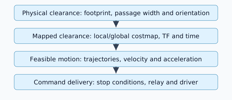
물리적 형상 확인
폭 0.60m의 로봇이 0.80m 폭의 복도 중앙에 정렬되어 있으며 양쪽에 0.10m의 여유 공간이 있습니다. 이 정적 계산에는 위치 오차, 매핑된 벽 두께, 페이로드 및 회전 중 모서리 스윕이 제외됩니다. 직사각형의 필요한 너비는 방향에 따라 달라집니다.
풋프린트는 다각형을 나타내며, robot_radius는 원형 근사치를 제공합니다. 구성된 외곽선을 RViz와 비교하여 미터 단위의 거리, base_link 원점, 돌출된 센서 또는 하중을 확인하십시오. Nav2 튜닝 가이드에서 형상 및 비용 필드를 다룹니다. 정지 지점을 제거하기 위해 외곽선을 실제 로봇보다 작게 줄이지 마십시오.
비용은 물리적 벽과 동일하지 않습니다.
장애물 레이어는 관측값을 통합하며, 인플레이션은 장애물 주변에 거리에 따라 달라지는 비용을 분산시킵니다. inflation_radius는 그 범위를 설정하고, cost_scaling_factor는 지수적 감소를 제어합니다. 다른 조건이 고정된 경우, 스케일링 계수가 클수록 감소 속도가 빨라집니다. 인플레이션 레이어 매개변수를 참조하십시오.
모든 고비용 영역이 절대적으로 접근 금지 영역은 아니며, inflation_radius만으로는 최소 본체 간격을 보장할 수 없습니다. 충돌 검사, 풋프린트 및 각 플래너/컨트롤러의 비용 사용량을 고려하십시오. 전역 지도에서 통행이 허용되지만 로컬 지도에 이전 장애물이 남아 있는 경우, 먼저 장애물 제거, 관측 범위 및 유효한 TF 타임스탬프를 확인하십시오.
실행 가능한 동작에 경로 연결
경로는 이동 경로를 지정합니다. 컨트롤러는 현재 속도 및 제약 조건에 맞는 동작을 생성해야 합니다. 좁은 공간에서의 큰 방향 전환, 최소 회전 반경을 가진 차량에 요구되는 제자리 회전 또는 가속도 제한으로 인해 후보 동작이 실행 불가능해질 수 있습니다.
컨트롤러 서버 문서에서 컨트롤러, 진행 검사기 및 목표 검사기 선택에 대해 설명합니다. 진행과 도착은 별개의 조건입니다. 플러그인별 제약 조건을 검사하기 전에 플러그인 이름과 오류를 기록하십시오.
명령이 사라지는 위치 추적
| 관측 | 다음 검사 |
|---|---|
| 컨트롤러가 유효한 명령을 생성할 수 없음 | 로컬 비용 지도, TF, 동작 제한 및 후보 궤적 |
| 컨트롤러 출력은 0이 아니지만 최종 출력은 0입니다 | 스무더, 충돌 모니터, 정지 입력 및 명령 우선순위 |
| 최종 출력은 0이 아니지만 바퀴가 움직이지 않습니다 | 토픽/유형, 드라이버, 활성화 상태 및 제어 모드 |
| 로봇이 움직이지만 빠르게 오류를 보고합니다 | 주행 거리 측정값과 실제 이동 및 진행 상황 |
/cmd_vel라는 토픽이 최종 단계라고 가정하지 마십시오. 구성에는 중간 토픽이 있으며 Twist 또는 TwistStamped를 사용할 수 있습니다. ros2 topic info <actual-topic> --verbose를 사용하여 실제 게시자, 구독자 및 유형을 확인하십시오. 정지 기능을 비활성화하는 대신 정지를 유발한 조건을 진단하십시오.
한 번에 하나의 변경 사항만 평가하십시오
통로, 초기 자세, 목표, 지도 및 입력 로그를 수정하십시오. 한 항목을 변경한 다음 최소 간격, 정지 횟수, 명령 및 오류 원인, 도착 시간을 비교하십시오. 0.10m의 산술 예제는 안전 작동 간격을 설정할 수 없습니다. 실제 치수, 오류 및 작동 조건은 별도로 평가해야 합니다.
시작 자체가 불안정하면 최소한의 Nav2 설정으로 돌아가십시오. 안정적인 구성은 매핑 오류와 드라이버 오류를 더 쉽게 구분할 수 있도록 해줍니다.
댓글
먼저 로그인해 주세요.
아직 데이터가 없습니다.